22
PARTS REQUIRED
q
{1} 740mm Split Elevator Pushrod Assembly
q
{2} Nylon Clevises
q
{1} Adjustable Servo Connector Assembly
q
{2} Nylon Control Horn w/Backplates
q
{4} 2mm x 25mm Machine Screws
ELEVATOR PUSHROD
INSTALLING THE CONTROL HORNS
q
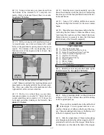
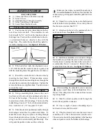
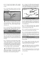
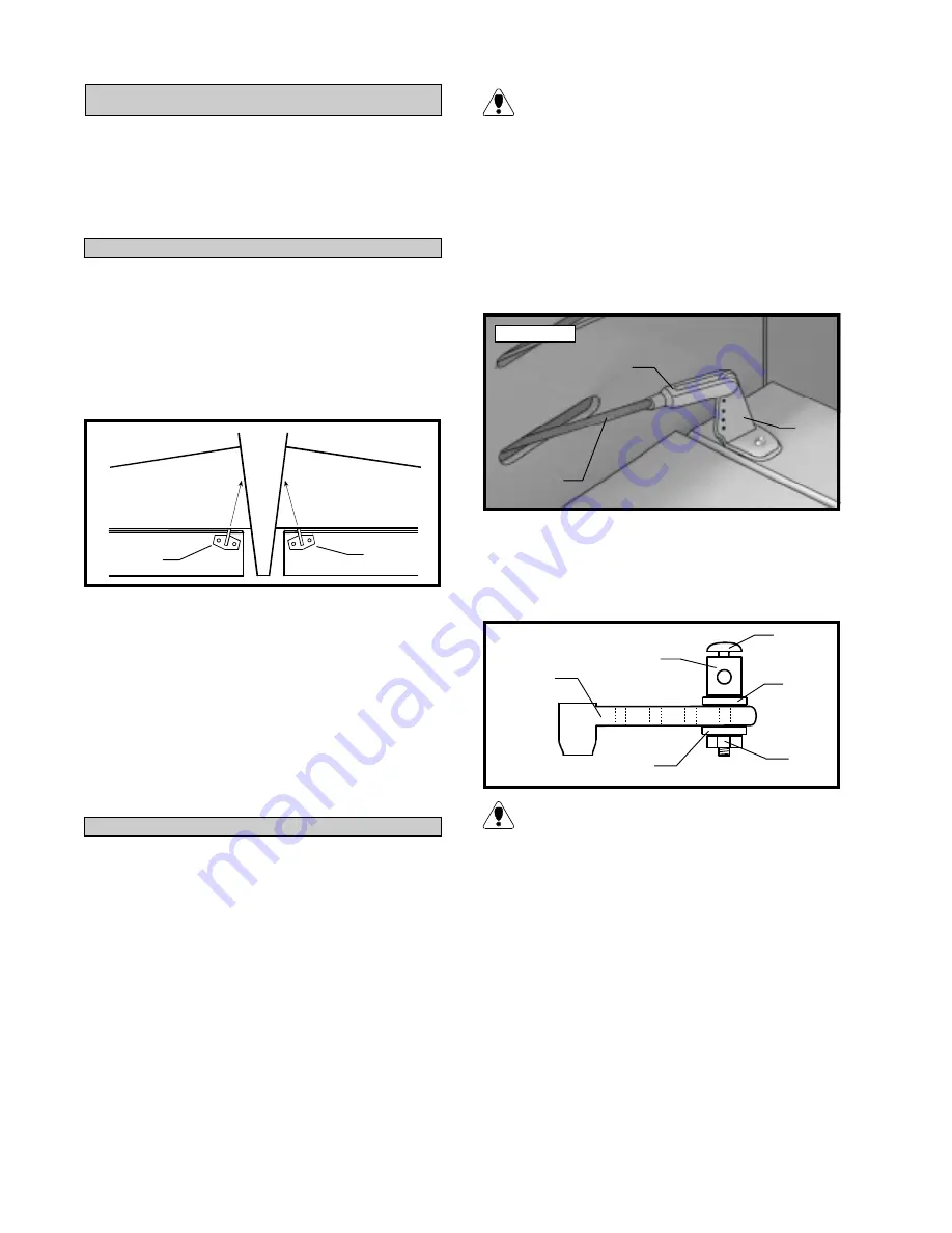
1) Position one elevator control horn on the bot-
tom of each elevator half. The centerline of each
horn should be 5/8” out from the fuselage sides at
the hinge line. Position the control horns so the cle-
vis attachment holes are directly in-line with the
hinge lines. The control horns should be angled to-
wards the fuselage sides. See figure # 18 below.
q
2) When satisfied with the alignment, use a
3/32” drill bit, and the control horns as a guide, and
drill the mounting holes through the elevator halves.
q
3) Mount the control horns to the elevators by
inserting the four 2mm x 25mm machine screws
through the control horn mounting bases, through the
elevator halves and into the backplates. Tighten the
screws, but do not overtighten them. You do not want
to crush the wood.
Figure # 18
q
4) Using a modeling knife, remove the cover-
ing from over the two elevator pushrod exit slots in
the rear of the fuselage. The center of each slot is
located on each side of the fuselage, 4” in front of the
rudder hinge line and 1” below the horizontal stabi-
lizer. Each slot is 1-1/2” long and 3/16” tall.
q
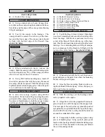
5) Slide the elevator pushrod assembly through
the fuselage and out the two pushrod exit holes. To
make this easier, drop two pieces of string through
the exit holes and into the servo bay. Tie one piece of
string to each wire and carefully pull the string. This
will guide the pushrod wires out the exit holes.
INSTALLING THE ELEVATOR PUSHROD
Make sure that when you install the pushrod, it
is installed below the rudder cables and that the
cables do not get wrapped around the pushrod wires
or dowel.
q
6) Thread two nylon clevises onto the threaded
ends of both elevator pushrods. For security, thread
the clevises on no less than 5/16”.
q
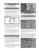
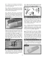
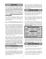
7) Attach each clevis to the outermost hole in
each control horn. See photo # 43 below.
Photo # 43
q
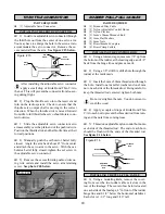
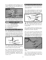
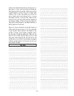
8) Install one adjustable servo connector through
the fourth hole out from the center of one servo arm.
You may have to enlarge the hole in the servo arm to
accommodate the servo connector. Remove the ex-
cess material from the arm. See figure # 19 below.
Figure # 19
After installing the adjustable servo connector
apply a small drop of Kwik Bond thin C/A to
the nut. This will prevent the connector from loosen-
ing during flight.
q
9) Slide the elevator pushrod wire through the
hole in the adjustable connector.
q
10) Use a couple of pieces of masking tape to
hold each elevator half in neutral.
q
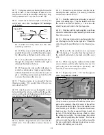
11) Plug the elevator servo into the receiver and
center the servo. Place the servo arm onto the servo.
The servo arm should be perpendicular to the fuselage
sides and point towards the middle of the fuselage.
Pushrod
Wire
Clevis
Control
Horn
Servo
Arm
Set
Screw
Servo
Connector
Washer
Washer
Nut
Control
Horn
Control
Horn


