7
The heat shrink tubing will prevent the plugs
from coming apart during assembly and more
importantly during flight. If you don't use heat shrink
tubing, electrical tape works well also.
q
19) Using the throttle pushrod wire as a guide,
insert one end through the precut servo lead hole in
the root rib, through the center ribs and into the servo
bay in the middle of the wing. Using masking tape,
tape the servo lead to the end of the wire. Carefully
pull the wire out of the wing while guiding the servo
lead out. When you have pulled the servo lead out,
remove it and the masking tape from the wire.
q
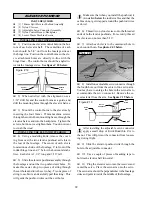
20) Set the servo hatch in place on the bottom
of the wing. The hatch should be orientated with the
servo arm toward the wing tip and up towards the
leading edge.
q
21) Using a ruler and a pen, measure and mark
the four mounting hole locations onto the hatch. The
holes should be located 1/8” in from each edge.
q
22) Drill 5/64” pilot holes through the hatch and
into the hardwood blocks beneath it at the locations
marked. Be careful not to drill through the top of the
wing! Remove the hatch and enlarge the holes in
only the hatch using a 7/64” drill bit. Reinstall the
hatch using the four 2.5mm x 12mm wood screws.
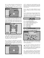
See photo # 3 below.
Photo # 3
q
23) Repeat steps # 17 - # 22 for the second servo
hatch assembly.
INSTALLING THE DIHEDRAL BRACE
q
24) Look at the surface of each root rib on both
wing halves. Notice how the excess covering mate-
rial overlaps onto them. Using a modeling knife, care-
fully cut away the covering from both of the root ribs.
Leave about 1/16” of covering overlapping so it does
not pull away.
It is important that the covering be removed
from the root ribs. This will ensure an adequate
wood-to-wood glue joint and prevent wing failure
during flight.
q
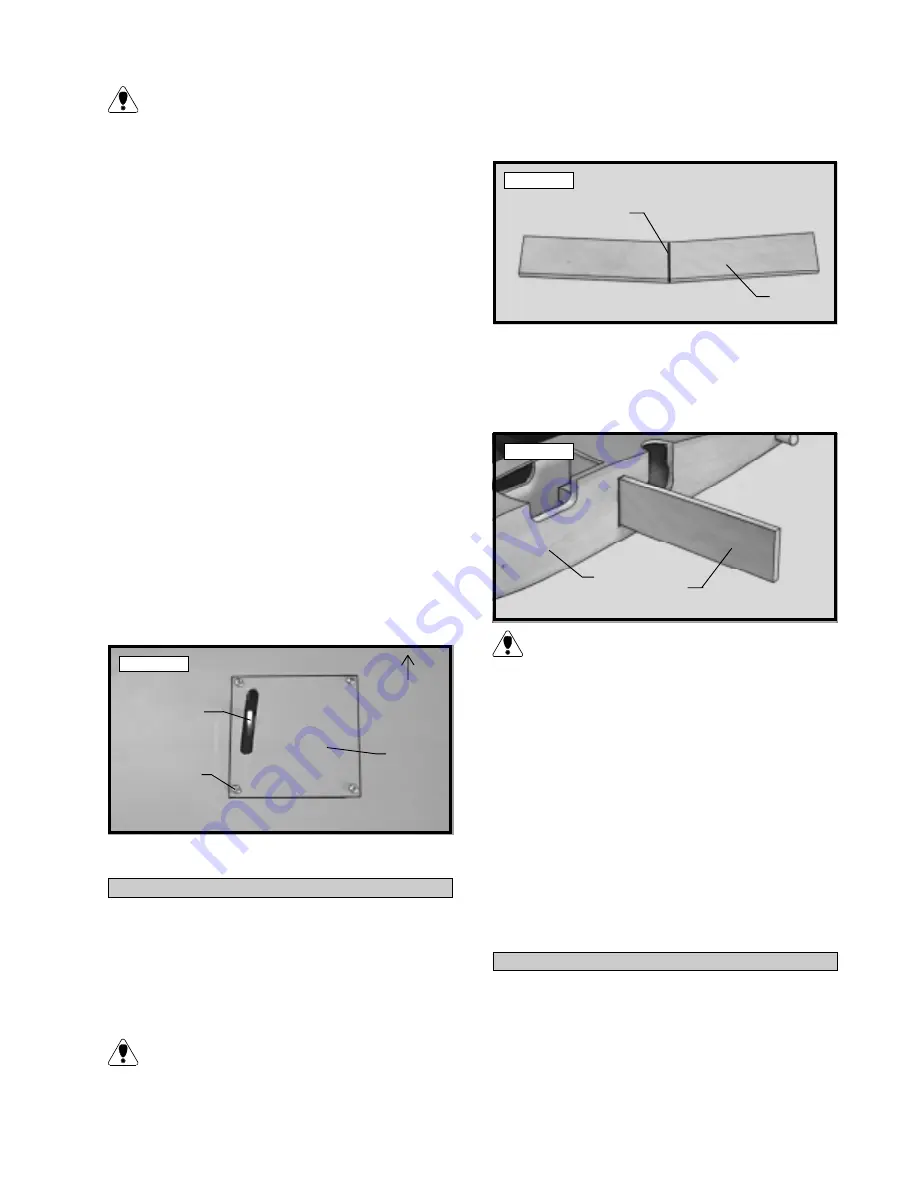
25) Using a ruler and a pen, locate and mark
the centerline of the plywood dihedral brace. Draw
one vertical line at this location on each side. See
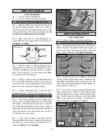
photo # 4 below.
Photo # 4
q
26) Test fit the dihedral brace into the plywood
box in each wing half. The brace should slide into
each wing half up to the centerline. If it does not,
remove the brace and lightly sand the edges and tips
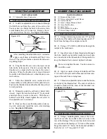
until the proper fit is obtained. See photo # 5 below.
Photo # 5
The dihedral brace is cut in the shape of a "V".
The "V" shape should face the top surface of
the wing when the brace is installed.
q
27) Test fit both of the wing halves together with
the dihedral brace temporarily installed. Do not use
glue at this time! The wing halves should fit to-
gether tight with little or no gaps in the center section
joint. If the center section joint is not tight, remove
the wing halves and lightly sand the edges and tips of
the dihedral brace. Test fit the wing halves together
with the dihedral brace installed again. Repeat until
you are satisfied with the fit of the wing halves.
q
28) When satisfied with the fit of the wing
halves, remove the wing halves and the dihedral brace.
q
29) Mix a generous amount of Kwik Bond 30
Minute Epoxy. Working with only one wing half for
now, apply a thin layer of epoxy inside the plywood
dihedral brace box and to only half of the dihedral
brace. Make sure to cover the top and bottom as well
as the sides, and use enough epoxy to fill any gaps.
JOINING THE WING HALVES
Servo
Hatch
Servo
Arm
Leading
Edge
Wood
Screw
Dihedral
Brace
Draw
Centerline
Dihedral
Brace
Root
Rib


