8
q
30) Slide the dihedral brace into the plywood
box up to the centerline. Remove any excess epoxy
before it dries using a paper towel and rubbing alco-
hol. Allow the epoxy to cure before proceeding.
q
31) Once the epoxy has cured, trial fit both wing
halves together to double check that the wing halves
still fit correctly.
q
32) Mix a generous amount of Kwik Bond 30
Minute Epoxy. Apply a thin layer of epoxy to the
exposed half of the dihedral brace, the inside of the
plywood box in the second wing half and the entire
surface of both root ribs. Make sure to use enough
epoxy to fill any gaps.
q
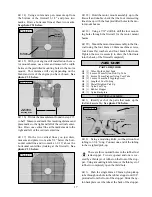
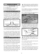
33) Slide the two wing halves together and care-
fully align them at the leading and trailing edges.
Wipe away any excess epoxy using a paper towel
and rubbing alcohol. Use masking tape to hold the
two wing halves in place until the epoxy cures. See
photo # 6 below.
Photo # 6
q
34) When the epoxy has fully cured, double
check the center section joint. If any gaps are present,
mix a small amount of Kwik Bond 30 Minute Epoxy
and carefully fill any remaining gaps. Allow the ep-
oxy to fully cure before proceeding.
PARTS REQUIRED
OPTIONAL FIXED MAIN GEAR
INSTALLING THE MAIN GEAR STRUTS
q
{2} Prebent Main Gear Wires
q
{2} 50mm Diameter Wheels
q
{4} Landing Gear Straps
q
{8} 2.5mm x 12mm Wood Screws
q
{2} Wheel Collars w/Set Screws
q
{2} Nylon Spacers
q
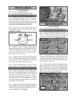
1) Using a modeling knife, remove the cover-
ing from over the two main gear mounting slots lo-
cated in the bottom of the wing. One slot is located
in each wing half, 8-3/4” out from the centerline of
the wing and 1-1/4” back from the leading edge. The
slot is 2-1/4” long.
Photo # 7
q
7) Repeat steps # 2 - # 6 for the second landing
gear wire.
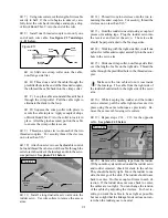
Photo # 8
INSTALLING THE MAIN GEAR WHEELS
q
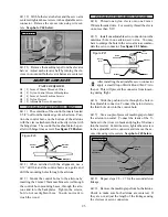
8) Slide one nylon spacer, then one wheel and
one wheel collar with set screw onto each axle. Make
sure the wheels spin free and tighten the set screws in
the wheel collars. See photo # 8 below.
Do not remove the covering from over the pre-
cut optional retract mounting holes, strut chan-
nels or wheel wells.
q
2) Insert the 90º bend of one main gear wire into
the rear hole in one mounting slot. The coiled spring
in the gear wire should be facing the trailing edge of
the wing.
q
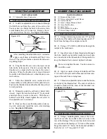
3) The gear wire is held in place using two land-
ing gear straps and four 2.5mm x12mm wood screws.
The straps should be located equal distance from the
front of the gear wire and the back of it.
q
4) Using the landing gear straps as a guide, mark
the locations of the four 2.5mm x 12mm mounting
screws onto the wing.
q
5) Remove the straps and the gear wire. Drill
four 5/64” holes into the wing for the wood screws.
Be careful not to drill through the top of the wing!
q
6) Reinstall the gear wire and install the straps
using the four 2.5mm x 12mm wood screws. Tighten
them completely to secure the gear wire in place. See
photo # 7 below.
Servo
Lead
Exit
Landing Gear
Wire
Mounting
Strap
Wood
Screw
Axle
Nylon
Spacer
Wheel
Collar
Set
Screw
Wheel
Wing
Joint
Trailing
Edge


