9
PARTS REQUIRED
OPTIONAL RETRACT MAIN GEAR
INSTALLING THE RETRACT MECHANISMS
q
{2} 50mm Diameter Wheels
q
{2} Molded Plastic Retract Gear Covers
q
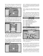
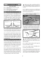
1) Using a modeling knife, remove the cover-
ing from over the two sets of precut wheel wells, gear
strut channels and retract mounting blocks in the bot-
tom of the wing. See photo # 9 below.
Photo # 9
q
2) Working with one wing half at a time, trial
fit the retract mechanism onto the hardwood mount-
ing rails.
The spacing between the two hardwood rails
should be sufficient for most popular brands of
retracts. If your retract mechanism is wider, you will
need to trim equal amounts of material off of the in-
side edge of each hardwood rail. If this is necessary,
we recommend using a Dremel Tool with a sanding
drum attachment.
q
3) When satisfied with the fit of the mechanism,
install the retract onto the rails. Drill 5/64” pilot holes
through the rails to prevent the wood from splitting
when you install the mounting screws. Be careful
not to drill through the top of the wing!
q
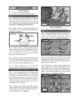
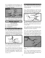
4) Install the retract using the mounting screws
provided with the retract. Tighten the screws com-
pletely. See photo # 10 below.
Photo # 10
q
5) Repeat steps # 2 - # 4 for installing the sec-
ond retract mechanism.
INSTALLING THE RETRACT SERVO
q
6) Install the rubber isolation grommets and
brass collets onto your retract servo. Place the servo
onto the preinstalled rails in the servo compartment
in the top of the wing. The servo output shaft should
face the leading edge of the wing.
q
7) Using a 1/16” drill bit, drill pilot holes through
the rails for the mounting screws. Be careful not to
drill through the bottom of the wing!
q
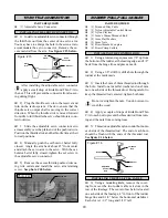
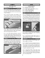
8) Secure the servo in place on the rails using
the mounting screws provided with the servo. See
photo # 11 below.
Photo # 11
INSTALLING THE RETRACT LINKAGE
q
9) Using wire cutters, cut both 12” 2-56 threaded
rods (not included) to 5” long. Thread one nylon cle-
vis (not included) onto each of the two rods.
q
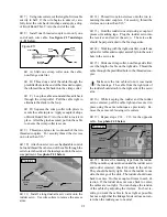
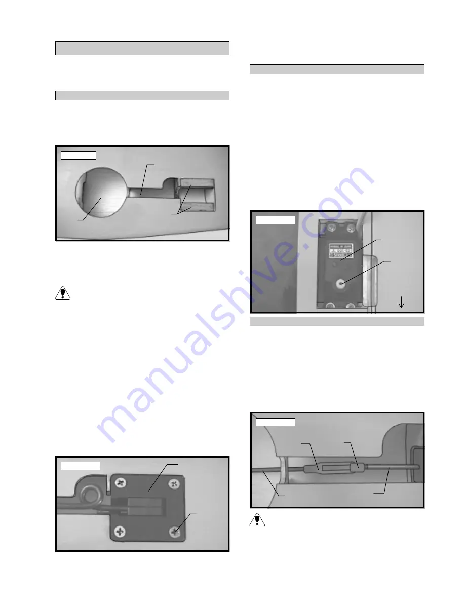
10) Slide the two threaded rods, with the clev-
ises attached, through the precut slots in the ribs, up
to the retract mechanism. Snap the clevises onto the
adjustable control horns. See photo # 12 below.
Photo # 12
The easiest way to get the threaded rods through
the slots is to insert the clevis end first through
the retract servo opening. They will slide through the
slots, up to the retract mechanism without any bend-
ing necessary.
Wheel
Well
Strut
Channel
Mounting
Blocks
Retract
Servo
Output
Shaft
Leading
Edgle
Pushrod
Wire
Nylon
Clevis
Adjustable
Control
Horn
Retract
Arm
Retract
Mechanism
Mounting
Screw
(not included)


