background image

25

Need help or have any questions?  Call us at 1-714-963-0329 or send us an Email at service@globalhobby.net

Kwik Bond 5 Minute Epoxy

Wire Cutters

Excel Modeling Knife

Scissors

220 Grit Sandpaper w/Sanding Block

Paper Towels

YOU'LL NEED THE FOLLOWING PARTS FROM THE KIT:

(1) Clear Canopy

(1) Nose Cone

(1) Plastic Switch Mount - Optional

(2) M2 x 5 Wood Screws - Optional

SECTION 10:  FINAL ASSEMBLY

(1) Velcro

®

 Strip

(1) Double-Sided Foam Tape

(1) Decal Set

YOU'LL NEED THE FOLLOWING TOOLS AND SUPPLIES:

Rubbing Alcohol

NHP Epoxy Mixing Sticks

NHP Epoxy Mixing Cups

Solder

Heat-Shrink Tubing (Assorted Sizes)

Step 1:  Installing the Nose Cone

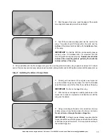
Using a pair of scissors, cut out the nose cone along its base, making sure to completely remove the molded radius.

Using 220 grit sandpaper with a sanding block, sand the back of the nose cone smooth and straight.

Using a thin layer of 5 minute epoxy, glue the nose cone

onto the fuselage.  Remove any excess epoxy using a paper
towel and rubbing alcohol, and hold the nose cone in place
until the epoxy sets up.

IMPORTANT

  Remember to roughen the gluing surfaces

with 220 grit sandpaper before gluing the nose cone into place.

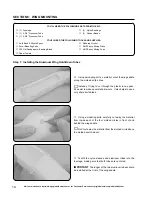
Using a pair of scissors, carefully cut out the clear canopy along the molded scribe lines.

IMPORTANT

  Be careful not to cut off the mounting tabs on the front and sides of the canopy!

Using 220 grit sandpaper with a sanding block, sand the edges of the canopy smooth and straight.

Step 2:  Installing the Canopy

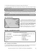
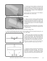
Set the canopy into the molded recess in the fuselage

and mark the locations of the three mounting tabs onto the
fuselage using a pencil.

Remove the canopy and use a sharp modeling knife to

cut thin slots through the fuselage for the tabs to slide into.

IMPORTANT


 Cut the slots on the inside edge of the molded

recess and no larger than the size of the mounting tabs.

Summary of Contents for Wattage Turbo Hawk EDF

Page 1: ...ttage Turbo Hawk EDF is distributed exclusively by Global Hobby Distributors 18480 Bandilier Circle Fountain Valley CA 92708 All contents copyright 2002 Global Hobby Distributors Version V1 0 December...

Page 2: ...assembled product By the act of using the final user assembled product the user accepts all resulting liability FOR YOUR INFORMATION To make your modeling experience totally enjoyable we recommend th...

Page 3: ...Bandilier Circle Fountain Valley CA 92708 Phone 714 963 0329 Fax 714 964 6236 Email service globalhobby net INTRODUCTION Thank you for purchasing the new Wattage Turbo Hawk EDF Before completing the...

Page 4: ...you choose should be capable of handling no less than 12 15 amps continuous current Again lighter is better Your ESC should weigh no more than 1 ounce including the wiring and switch Important Note W...

Page 5: ...ou to remove the wing As a second note to the above about current loss it s also imperative that you use high quality connectors to connect the flight battery to the ESC Do not use the Tamiya connecto...

Page 6: ...ge IC 15A Micro ESC QTY 1 131174 Wattage 16 Gauge Silicon Motor Wire QTY 1 128539 Wattage 10 Cell 800Mah 5 4AAA NiMH Flight Battery QTY 1 130108 Wattage PF 12 AC DC Park Flyer Charger QTY 2 625085 Dea...

Page 7: ...n Capacitors MISCELLANEOUS FUSELAGE PARTS 1 Elevator Servo Mounting Board 1 Foam Elevator Servo Tray 1 Plastic Switch Mount Optional 2 M2 x 5 Wood Screws Optional 1 Velcro Strip 1 Double Sided Foam Ta...

Page 8: ...e red dot next to it is the positive terminal IMPORTANT The motor wires must be 10 long to reach the fuselage and still have some extra left to work with Carefully solder the three noise suppression c...

Page 9: ...od idea to check We suggest using a propeller balancer to do this If the impeller is out of balance apply a small piece of electrical tape to the back side of the light blade and re test until you are...

Page 10: ...be flush with the root end of the wing panel Repeat the previous procedures to cut a notch in the root end of the second wing panel It s important that the notches in each wing panel line up with each...

Page 11: ...hol and hold the plate in place until the epoxy sets up Step 3 Installing the Aileron Torque Rods Working with one aileron for now place one torque rod over the molded hinge line and align it so that...

Page 12: ...mportant Tip Do not glue the torque rod to the wing or to the leading edge of the aileron If you do this the aileron will be glued solid and won t be able to pivot up and down After the epoxy has set...

Page 13: ...ont of the torque rods It s very important to the integrity of the wing that the reinforcement board be adhered to the wing along its entire surface Carefully apply the reinforcement board strip to th...

Page 14: ...g the Aluminum Wing Hold Down Tubes Using a modeling knife carefully cut out the wing saddle along the molded scribe lines Instead of trying to cut through the plastic in one pass it s easier to make...

Page 15: ...of the wing the glue joint should line up with the fuselage mold lines at the front and back of the wing saddle When satisfied with the alignment hold the wing securely into place using two rubber ba...

Page 16: ...epoxy using a paper towel and rubbing alcohol and hold the stabilizer in place and aligned until the epoxy sets up WARNING Don t apply epoxy to the end of the elevator You don t want to glue the elev...

Page 17: ...g board when you install them later Using a modeling knife carefully trim away the plastic burrs left from drilling the holes Slide the horizontal stabilizer assembly into place Push the stabilizer as...

Page 18: ...aded Wires 1 Nylon Control Horn 1 Nylon Control Horn Backplate SECTION 8 CONTROL SYSTEMS INSTALLATION 3 Nylon Clevises 2 Nylon Adjustable Control Horns 1 Elevator Servo Mounting Board 1 Foam Elevator...

Page 19: ...od Assembly Install the rubber grommets and brass collets onto the elevator servo mounting lugs When installing the collets make sure that the flanges are toward the bottom of the mounting lugs Test f...

Page 20: ...on far enough to leave room for adjustments later Slide the plain end of the pushrod wire through the hole in the back of the fuselage then carefully snap the clevis into the elevator control horn IM...

Page 21: ...t this location Do this on the bottom of the wing Place your aileron servo on the bottom of the wing aligning the front of the case with the mark you drew IMPORTANT Align the front of the case with th...

Page 22: ...h the servo horn to the servo making sure that it s centered You will have to enlarge the holes in the servo arms using a 1 16 drill bit so that you can attach the pushrods Install and tighten the ser...

Page 23: ...nit fits into the molded step in the back of the nacelle You will have to push the fan unit down into place firmly to get it to seat properly in the molded step When you have the fan unit seated prope...

Page 24: ...in the bottom of the nacelle over the plywood mounting post in the wing To align the assembly properly the nacelle should be perpendicular to the top of the wing when viewed from the front and the na...

Page 25: ...cone smooth and straight Using a thin layer of 5 minute epoxy glue the nose cone onto the fuselage Remove any excess epoxy using a paper towel and rubbing alcohol and hold the nose cone in place until...

Page 26: ...fuselage using a small piece of clear decal or tape Important Tip If you run the antenna through the inside of the fuselage make sure that the antenna is not wrapped around or otherwise touching the...

Page 27: ...ward wing hold down tube using a piece of double sided foam tape IMPORTANT If your ESC features a micro switch we suggest mounting it into the side of the fuselage using the plastic switch mount and t...

Page 28: ...itch Do not start to move the C G back until you are comfortable with the flight characteristics of the airplane Balance the Turbo Hawk EDF with the flight battery installed Measure and draw two marks...

Page 29: ...e following A Plug the flight battery into the ESC and turn on the radio system WARNING Do not turn the receiver on unless the transmitter is turned on first Always turn the transmitter on first Never...

Page 30: ...the safety of others Please read and understand these safety guidelines before going out to the flying field for the first time Do not test fly your model for the first time without first having it s...

Page 31: ...ght battery before every flight and the ninth one about getting used to the fact that this is not a propeller driven aircraft so it will behave differently in the air In the Air In the air the Turbo H...

Page 32: ...order directly from us at the address shown below SECTION 15 REPLACEMENT PARTS Global Services 18480 Bandilier Circle Fountain Valley CA 92708 Phone 714 963 0329 Fax 714 964 6236 On the Web http glob...

Page 33: ...33 Need help or have any questions Call us at 1 714 963 0329 or send us an Email at service globalhobby net...

Page 34: ...34 Visit our website at http watt age globalhobby com or for Customer Service at http globalservices globalhobby com...

Page 35: ...Service Department to resolve the problem Yes No 7 Was any of the assembly difficult for you If yes please explain Yes No ____________________________________ ____________________________________ ____...

Page 36: ...com Fold along dotted line Fold along dotted line Global Hobby Distributors Attn Global Services 18480 Bandilier Circle Fountain Valley CA 92728 8610 Post Office will not deliver without proper posta...

Reviews: