Quick Start Guide
To install the lock
1.
Remove the existing lock.
2.
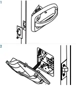
Position the exterior lock assembly
(with keypad) on the outside of the
door, ensuring the plunger assembly
is positioned at the edge of the door as
shown (1).
3.
Using the 2 #8-32 x 3/8” flat head
screws provided, install the door edge
cover on the edge of the door. Ensure the
door edge cover is flush to the edge of
the door.
4.
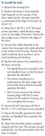
Connect the cable attached to the
interior lock housing to the cable attached
to the exterior lock housing. Position the
cable inside the door as shown (2) to
avoid pinching and binding.
5.
Position the interior lock assembly on
the door, ensuring:
y
The deadbolt post is inserted in the
red deadbolt lever so that the lever
operates the deadbolt.
y
The interior handle post is
positioned on the door edge side
of the latch tab so that the handle
operates the latch.
y
The 3 screw posts on the interior
housing align with the 3 screw
bosses on the exterior housing. Do
not overtighten the screws.
6.
Secure the lock housings with the 4
#8-32 x 7/8” oval head screws provided.
7.
Ensure the handle operates the latch
and the red deadbolt lever operates the
deadbolt.
8.
Check that the strike plate is properly
aligned with the lock. The plunger should
extend fully into the strike plate when the
door is locked.
Guide de démarrage rapide
Installer le verrou
1.
Supprimer le verrou existant.
2.
Positionnez le verrou extérieur (avec
le clavier) à l’extérieur de la porte,
en veillant à ce que le plongeur soit
positionné sur le bord de la porte, comme
indiqué (1).
3.
À l’aide des 2 vis à tête plate
n ° 8-32 x 3/8” fournies, installez le
couvercle du bord de la porte sur le bord
de la porte. Assurez-vous que le couvercle
du bord de la porte est bien aligné sur le
bord de la porte.
4.
Connectez le câble attaché au boîtier
du verrou intérieur au câble attaché au
boîtier du verrou extérieur. Placez le câble
à l’intérieur de la porte comme indiqué
(2) pour éviter les pincements et les
blessures.
5.
Positionnez le verrou intérieur sur la
porte en veillant à:
y
La borne de pêne dormant est
insérée dans le levier de pêne
dormant rouge afin que ce dernier
actionne le pêne dormant.
y
Le montant intérieur de la poignée
est positionné sur le côté du bord de
la porte de la languette du loquet
de sorte que la poignée actionne
le loquet.
y
Les 3 bornes à vis du boîtier
intérieur sont alignées sur les
3 bosses d e la vis du boîtier
extérieur. Ne serrez pas trop les vis.
6.
Fixez les boîtiers de verrouillage à
l’aide des 4 vis à tête ovale
n ° 8-32 x 7/8” fournies.
7.
Assurez-vous que la poignée actionne
le loquet et que le levier de pêne dormant
rouge actionne le pêne dormant.
8.
Vérifiez que la gâche est correctement
alignée avec le verrou. Le piston doit
s’étendre complètement dans la gâche
quand la porte est verrouillée.
Guía de inicio rápido
Para instalar la cerradura
1.
Retire la cerradura existente.
2.
Coloque el conjunto de la cerradura
exterior (con el teclado) en el exterior
de la puerta, asegurándose de que el
conjunto del émbolo esté colocado en el
borde de la puerta como se muestra (1).
3.
Usando los tornillos de cabeza plana
2 # 8-32 x 3/8” provistos, instale la
cubierta del borde de la puerta en el
borde de la puerta. Asegúrese de que la
cubierta del borde de la puerta esté al ras
del borde de la puerta.
4.
Conecte el cable conectado a la
carcasa de bloqueo interior al cable
conectado a la carcasa de bloqueo
exterior. Coloque el cable dentro de la
puerta como se muestra (2) para evitar
pellizcos y atascos.
5.
Coloque el conjunto de la cerradura
interior en la puerta, asegurándose de
que:
y
El poste del cerrojo se inserta en la
palanca roja del cerrojo para que
la palanca accione el cerrojo.
y
El poste interior de la manija se
coloca en el lado del borde de la
puerta de la pestaña del pestillo,
de modo que la manija acciona el
pestillo.
y
Los 3 postes de tornillo en la
carcasa interior se alinean con
las 3 protuberancias de tornillo
en la carcasa exterior. No apriete
demasiado los tornillos.
6.
Asegure las carcasas de bloqueo con
los tornillos de cabeza ovalada 4
# 8-32 x 7/8” provistos.
7.
Asegúrese de que el asa accione el
pestillo y la palanca roja del cerrojo
accione el cerrojo.
8.
Compruebe que la placa de contacto
esté correctamente alineada con el
bloqueo. El émbolo debe extenderse
completamente en la placa de protección
cuando la puerta está bloqueada.
Global Link Ultra ES Pro
Smart Lock
08/2021
www.c
pgbrands.com
1
2
Beeps Summary / Résumé des bips / Resumen de pitidos
1 beep / 1 bip / 1 pitido
Keypress / Appuyez sur la touche / Pulsación de tecla
2 beeps / 2 bips / 2 pitidos
Factory default code or user code entered / Code par défaut d’usine ou code d’utilisateur entré /
Código predeterminado de fábrica o código de usuario introducido
2 beeps (after 3 seconds) / 2 bips (après 3 secondes) / 2 pitidos (después de 3 segundos)
Programming mode entered / Mode de programmation entré / Modo de programación ingresado
2 ascending beeps / 2 bips ascendants / 2 pitidos ascendentes
Unlocking successful / Déblocage réussi / Desbloqueo exitoso
2 descending beeps / 2 bips descendants / 2 pitidos descendentes
Locking successful / Verrouillage réussi / Bloqueo exitoso
3 varied beeps / 3 bips variés / 3 pitidos variados
New code entered / Nouveau code entré / Nuevo código introducido
Programming successful / Programmation réussie / Programación exitosa
Reset successful / Réinitialisation réussie / Restablecer exitoso
4 quick beeps / 4 bips rapides / 4 pitidos rápidos
Incorrect code entered / Code incorrect entré / Código incorrecto introducido
4 quick, descending beeps / 4 bips rapides décroissants / 4 pitidos rápidos y descendentes
Low battery / Batterie faible / Batería baja
WARNING: Cancer and Reproductive Harm
www.P65Warnings.ca.gov
Summary of Contents for Ultra ES Pro
Page 3: ...1 2 2 ...


