background image

12

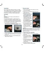
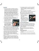
4. Close the tank 1 isolation valve (18).

5.  Disconnect the tank 1 inlet hose (25) from the combination 

valve (8), by sliding back the sleeve of the quick connect 

fitting and removing the inlet hose. 

Note.

 The inlet hose has been fitted with a special one way 

valve. On removal of the inlet hose there will be a slight 

discharge of air.
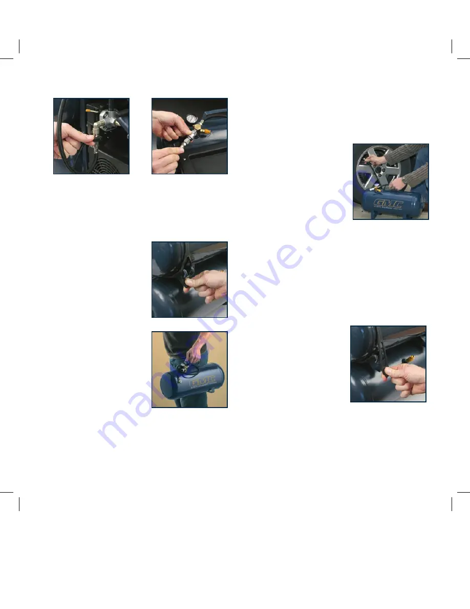
6. Place the tank 1 inlet hose 

(25) on the provided clip.

7. Disconnect the rubber support 

straps (22) by pulling them 

over the support brackets (23) 

to release the air tank.

WARNING.

 Be careful when 

releasing the straps they do have 

a tight fit.
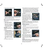
8. The tank has now been 

correctly disconnected from the 

air compressor unit. You can 

now move the tank freely  

by using the carry handle (20) 

to lift and move the tank. You 

can now use the removed tank. 

  The separated tank has two 

outlets that you can choose 

from;

a) the attached inflation hose; or

b) the provided quick connect coupler that you can connect 

another air hose to. This can be done by sliding back 

the sleeve of the quick connect coupler and inserting an 

air hose assembly that is fitted with a Nikko style fittings. 

Due to the limited supply of air it is recommended that 

the removable tank is fully charged with air prior to being 

removed.

Note.

 While the tank has been 

removed you can still use the 

master unit/compressor with only 

one tank. This can be done by 

simply reconnecting the master 

unit/compressor back to the power 

supply, and turning the unit on at 

the On/Off switch (2).

CAUTION.

 When using the master unit/compressor with 

the top tank removed always check to ensure that the air 

isolation vale (18) is in the off position. 

Installing the air tank:

1. Turn the On/Off switch (2) on the compressor to the  

off position.

2. Turn the power supply off and disconnect the power cable.
3. Lift the main handle (1) up and away from the portable 

tank location.

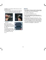
4. Sit the tank down on the 

support brackets (23).

5. Reconnect the rubber support 

straps (22) to the support 

brackets (23). 

Note.

 Grip the rubber straps at 

the fixed end and stretch evenly 

over the tank until the straps are 

connected securely to the support 

brackets.

WARNING.

 When extending the rubber straps be careful. If 

released early they can flick back and hurt you. Make sure 

that your face is at a safe distance from the rubber straps 

while they are being stretched. 

Summary of Contents for 2HP/1600W 32LT DUAL TANK COMPRESSOR WITH REMOVABLE TANK DTC32L

Page 1: ...s equipment operates from AC mains only High voltage used on this equipment Prior to servicing or removing the cover switch off the power supply remove plug from mains Ensure mains outlet is adequately rated for this unit Unit starts automatically Switch off power supply remove plug relieve air pressure prior to commencing service tasks DTC32L Air Compressor Tank capacity 32 litres Pump displaceme...

Page 2: ...luded accessories Only the power tool is covered under this warranty With continuing product development changes may have occurred which render the product received slightly different to that shown in this instruction manual Please ensure that you store your receipt in a safe place Conditions apply to the above warranty For full details of the warranty terms and conditions please refer to our webs...

Page 3: ...ld up of condensation open drain cock daily Read instruction manual prior to starting unit This equipment operates from AC mains only High voltage used on this equipment Prior to servicing or removing the cover switch off the power supply remove plug from mains Ensure mains outlet is adequately rated for this unit Unit starts automatically Switch off power supply remove plug relieve air pressure p...

Page 4: ...15psi Free air delivery 114 l min 4 CFM Pump displacement 206 l min 7 3 CFM Introduction Your new GMC power tool will more than satisfy your expectations It has been manufactured under stringent GMC Quality Standards to meet superior performance criteria You will find your new tool easy and safe to operate and with proper care it will give you many years of dependable service CAUTION Carefully rea...

Page 5: ...a heavier duty tool Never use a tool for a purpose for which it was not intended 7 Dress correctly Do not wear loose clothing or jewellery They can be caught in moving parts Rubber gloves and non slip footwear are recommended when working outdoors If you have long hair wear a protective hair covering 8 Use safety accessories Safety glasses and earmuffs should always be worn A face or dust mask is ...

Page 6: ...pressor in a well ventilated area Do not smoke while spraying Do not spray where sparks or flames are present Keep the compressor as far away from the spray area as possible The solvents trichloroethane and methylene chloride can chemically react with the aluminium used in some paint spray guns and form an explosion If these solvents are used ensure that only stainless steel spray equipment is con...

Page 7: ...ace prior to checking the oil level The oil level is required to be at the red dot on the oil level sight glass prior to use Use only oil grade specified in this instruction manual Note The compressor is supplied empty of oil It must be filled with oil before first use After using the compressor switch off the on off switch disconnect the power supply and open the outlet valves on both tanks to re...

Page 8: ...extremely dangerous and can whip around very quickly both with the capability of striking people and blowing foreign particles into the air Do not attempt to catch the air line but immediately keep bystanders well clear Disconnecting the remaining hose from the quick release fitting on the unit will automatically shut off the air supply Turn off the compressor at the On Off switch Contents of cart...

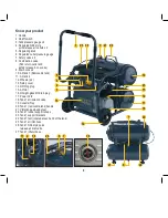
Page 9: ... Air tank 2 12 Wheels x 2 13 Safety cover 14 Oil filling plug 15 Air filter 16 Oil sight glass Oil drain plug 17 Power Cord 18 Tank 1 air isolation valve 19 Console Tray 20 Tank 1 removable tank handle 21 Vibration dampening feet 22 Tank 1 rubber support straps 23 Tank 1 support brackets 24 Tank 1 feet located at each end of the tank 25 Tank 1 air inlet hose 26 Tank 1 Nitto style quick release air...

Page 10: ... start routine 1 Ensure that the location for the compressor is clean dry and well ventilated 2 Ensure the crank case has been filled with oil and is at the correct level 3 Start the compressor by following the procedure in the section To start and stop the compressor Prior to the first time operation of the compressor open the drain cocks in both of the tanks 9 run the compressor for 20 30 minute...

Page 11: ...se the air pressure rotate the regulating valve clockwise To decrease the pressure rotate the regulating valve anti clockwise Note If you do not allow the air to discharge while you are setting the regulator the pressure as indicated on the regulated outlet gauge will be incorrect This gauge ONLY indicates the correct pressure while air is being discharged from the outlet 5 On completion of the ta...

Page 12: ...ly that is fitted with a Nikko style fittings Due to the limited supply of air it is recommended that the removable tank is fully charged with air prior to being removed Note While the tank has been removed you can still use the master unit compressor with only one tank This can be done by simply reconnecting the master unit compressor back to the power supply and turning the unit on at the On Off...

Page 13: ... is now ready for use WARNINGS 1 Never attempt to remove any electrical component whilst the compressor is connected to the power supply Switch off the power and remove the electrical plug 2 Do not adjust the safety valve 3 Do not use an electrical extension cable 4 Ensure that the lubricating oil is clean and that the oil level is maintained at the mid point of the red circle in the oil sight gla...

Page 14: ... service centre to repair or replace faulty parts Main compressor sticking tight Moving parts damaged by heat due to insufficient lubrication Use authorised service centre to check crankshaft bearings con rod piston rings etc and replace where necessary Moving parts damaged or blocked by foreign particle Vibration or abnormal noise Loose part Use authorised service centre to check and repair if ne...

Page 15: ...nd close the drain cock s Safety valve fully leaking Check out the condition of the safety valve If the valve is leaking immediately shut off the compressor and cease using Have the unit serviced checked by an authorised service centre and repaired Don t continue to use the unit with a leaking safety valve Air line hose leaking Examine the air hose for any holes and tears If you find any holes or ...

Page 16: ...ggested Remedy Excessive oil consumption Oil level too high Maintain the oil at the correct level Hole in oil filling plug 14 blocked Check and clean Piston ring and or cylinder worn or damaged Use authorised service centre to check and repair if necessary ...

Page 17: ...g is released the air discharge must stop WARNINGS Safety glasses must be worn when performing this test Do not have your face close to the safety valve when performing this test as air will discharge from the valve at a high force If the safety valve does not operate correctly in any way as described above turn off the compressor immediately and have the compressor and safety valve checked and te...

Page 18: ...rol or other cleaning agent 5 Never use caustic agents to clean plastic parts CAUTION Water must never come into contact with the tool Power cord maintenance Only an authorised service centre should replace the cordset or carry out other repairs If the cordset is damaged or worn have it repaired or replaced by an authorised service centre ...

Page 19: ...19 ...

Page 20: ...20 ...

Page 21: ...ew Zealand 7am 7pm 7days a week AEST Please note that if repair or replacement is required you must provide a valid original purchase receipt You will need the following details at hand to log your service request Personal details First Last name address pick up address contact phone numbers email address Product details Product number date of purchase retailer bought from State postcode receipt n...

Reviews: