3
An Important Message for Installers and Operators
These instructions include information intended to assure correct installation, operation and trouble-free
service. Prior to attempting installation, service or operation, be certain of the following:
1. You have fully read and understood these instructions
2. You have the tools required and sufficient training to use them.
3.You have met all code, installation and application restrictions.
4. You are familiar with the function and operation of the unit.
5.That these instructions are followed exactly as given.
Inspect for Damage
This unit was packaged and inspected at the factory and
was in excellent condition at the time of shipment. The
transit company or others involved in it’s handling are
responsible for loss or damage that may have occurred
after the unit left the factory. Inspect the underside of the
cabinet and packaging for damage such as a forklift
might cause. Also, look for bent components that might
indicate that the unit has been dropped. Open any
cartons that appear to have damage and inspect the
contents. Always attempt to inspect the unit prior to the
departure of the delivery driver so that the driver can
detail the damage on the freight bill. If damage is found
after uncrating, immediately call the delivery carrier and
request an inspection. Most carriers require that
inspections be done within 15 days of delivery. Retain all
packaging and crating materials for damaged units until
the inspection is complete.
Locating the Cabinet
Select a location where the cabinet will not be exposed
to heat sources such as sun through windows, heating
vents, etc. Extension cords should be avoided, so a
receptacle of the proper type and current rating should
be within 6 feet of the unit’s location.
CLEARANCE REQUIREMENTS: Allow a minimum of
twelve (12) inches between the top of the cabinet
and ceiling and a minimum of two (2) inches
between the back of the cabinet and wall for proper
air circulation through the condensing unit.
Installing the Cabinet
(Models with Top Mounted Compressors)
Whenever possible, leave the crate skid on the cabinet
until it is moved close to the final position. If the cabinet
must me moved through a narrow doorway, it may be
necessary to remove the crate skid. Wood runners are
provided on the underside of the cabinet for ease in
sliding.
The runners should be left attached to the
cabinet when the skid is removed and should remain
attached until after the legs are installed
.
The cabinet can then be pushed around more easily
without scratching the floor. The runners also prevent
damage to the electrical receptacle and condensate pan
hardware on the cabinet bottom. After the cabinet has
been moved to the approximate final location, remove
the package containing the legs from the cabinet interior.
Tape the doors to prevent accidental opening while
handling. Raise the sides of the cabinet high enough to
mount the legs at the locations provided on the bottom of
the cabinet. Level the cabinet by means of the leg
adjustments. The cabinet doors are self-closing, and the
cabinet must be level to operate properly.
Condensation Pan
(Models with Top Mounted Compressors)
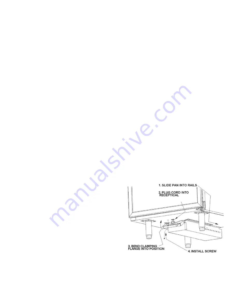
The condensate pan assembly mounts in the “track” pro-
vided on the underside of the cabinet. The pan assembly
must be pushed in from the front of the cabinet far
enough to be positioned under the condensate drain
tube on the backside of the cabinet.
NOTE: THERE IS A PROTECTIVE COVER OVER THE
ELECTRICAL RECEPTACLE ON THE CABINET BOT-
TOM WHICH MUST BE REMOVED AND DISCARDED
PRIOR TO THE CONDENSATE PAN INSTALLATION.
The pan assembly must be secured by a #10-32 thumb
screw and is designed to prevent accidental unplugging
of the pan supply cord. The pan must be in the correct
position to insert the thumb screw. Shut off the power
supply before plugging in pan supply cord.
Installing the Cabinet
(Models with Bottom Mounted Compressors)
To remove the skid the skid mounting clips, located
behind the front griII must be removed.


