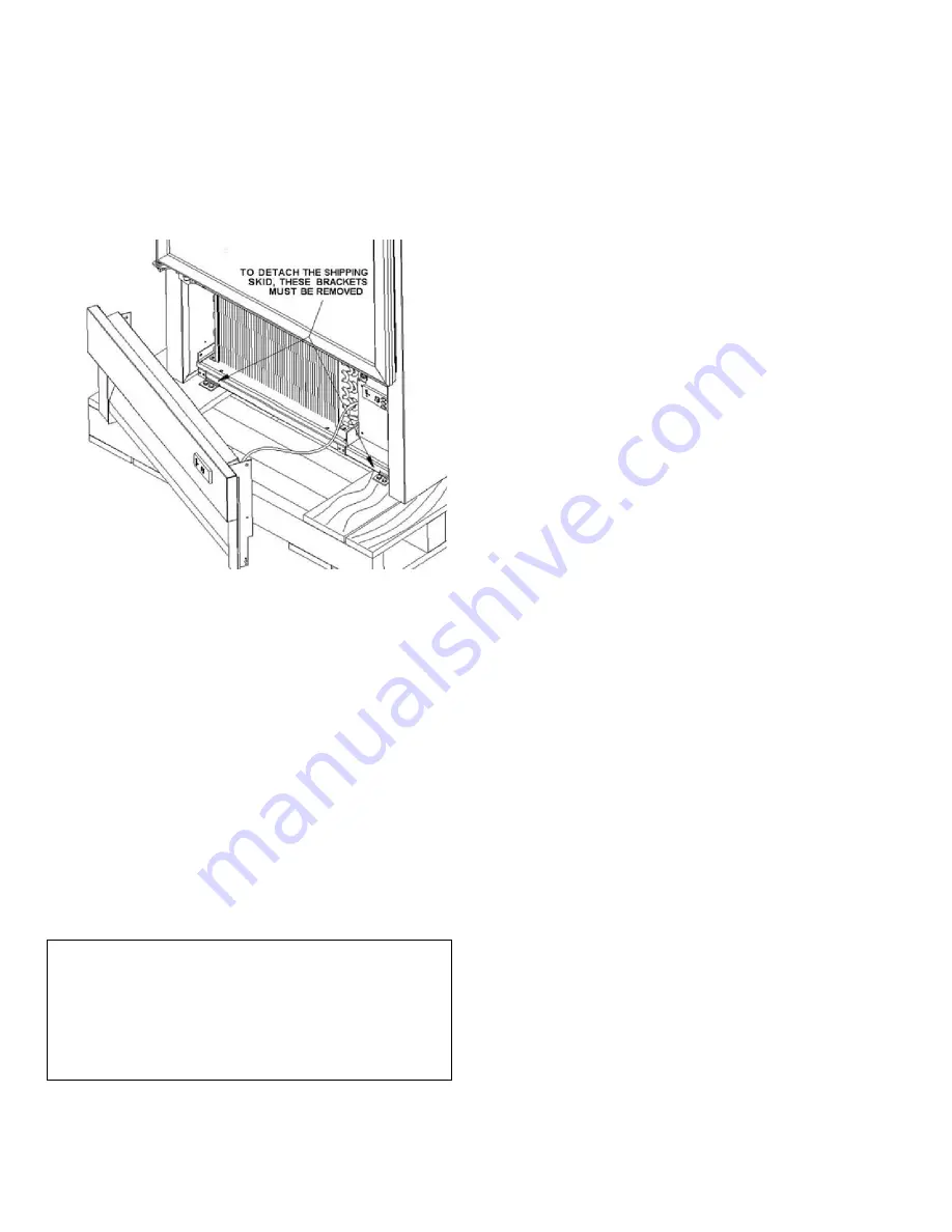
4
CAUTION: There is cable connecting the grill
mounted display to the control box. Take care to
avoid pulling on it.
Once the front clips are removed the cabinet can be slid
forward to clear the rear mounting clips. After removing
the skid, move the cabinet into location. Make sure the
cabinet is level so that the self-closing doors operate
properly.
Electrical Requirements
Check the electrical rating plate on the cabinet to be
sure the one required matches your requirements.
Check voltage and amp draw on the serial plate to
determine proper fuse and wire size.
CAUTION:
All cabinets must have a grounded
supply receptacle. The cord provided must be used
only with its ground pin intact.
It is recommended that a separate supply circuit be run
for each cabinet to prevent the possibility of another
appliance blowing a fuse, causing subsequent loss of
product. Caution: The insulated space of this cabinet is
sealed to maintain peak efficiency. Holes drilled in the
cabinet may destroy that seal and damage electrical
wiring located in the insulated space.
CAUTION
:
The insulated space of this cabinet is
sealed to maintain peak efficiency. Holes drilled in the
cabinet may destroy that seal or damage electrical
wiring located in the insulated space.
DAMAGED ELECTRICAL WIRING OR WET
INSULATION CAUSED BY DRILLING WILL VOID
THE WARRANTY.
N.S.F. Required Installation Procedures
Shelf Brackets:
To comply with NSF requirements, the shelves and
their brackets must be removable without the use of a
tool. At the time of initial installation, all shelf bracket
screws should be loosened with a tool and re-tightened
“hand tight”.
Floor sealing of cabinets without legs or casters:
(bottom mount cabinets only)
1) Remove front grill.
2) Seal around entire outside perimeter of cabinet
(except sides, if against wall) with an N.S.F.
approved sealant (GE-802, DOW-732).
3) Sealed joint should be smooth and easily cleanable.
4) Replace front grill.
Cabinet Start-up
Once the cabinet has been located in its permanent
location and the proper power and grounding has been
provided, the following items must be checked or
completed:
a.)
Cut and remove the compressor shipping strap
(where supplied) so the compressor “floats” freely.
b.)
Check for traces of oil on the compressor pan which
could mean a broken or leaking refrigeration line.-
UNDER NO CIRCUMSTANCE SHOULD THE
COMPRESSOR BE STARTED WHEN OIL IS
PRESENT UNTIL AFTER AN INSPECTION BY A
SERVICE TECHNICIAN.
c.)
INSPECT FACTORY WIRING FOR TERMINALS
THAT MIGHT HAVE LOOSENED DURING
SHIPPING TIGHTEN ALL SCREW TYPE
TERMINALS
d.)
Check the refrigeration lines to see that they are
'free" and no damage was done during shipping.
e.)
Check that the fan blade(s) rotate freely.
f.)
Turn on the main power switch. Once the compres-
sor starts, the voltage should be checked at the
compressor terminals to determine if there is
proper voltage to the compressor. The voltage
should not exceed the 10% above or below the
rated compressor voltage.
EXAMPLE: If the supply
voltage reads 115 volts with the unit off and it
drops below 103 volts once the compressor is
running, it may indicate that the supply wiring is
insufficient
.


