background image

June 2010
© 2010 Global Specialties
All rights reserved. 

Specifications are subject to change without notice.

All product names are trademarks of their respective companies.

Model 3600 User Manual_B.indd   2

7/2/2010   4:41:38 PM

Summary of Contents for 3600

Page 1: ...Model 3600 32 Channel Logic Analyzer Users Manual Test Equipment www globalspecialties com Innovative Training Solutions Model 3600 User Manual_B indd 1 7 2 2010 4 41 38 PM ...

Page 2: ... 2010 Global Specialties All rights reserved Specifications are subject to change without notice All product names are trademarks of their respective companies Model 3600 User Manual_B indd 2 7 2 2010 4 41 38 PM ...

Page 3: ...l 5 Data Entry 5 Number Input 5 Input Control 6 Cursor Control and Adjust knob 6 Sample Rates 6 Function Selection 6 Display Description 6 Waveform Interface Display 7 Data Interface Display 7 Trigger Interface Settings 7 Operating Instructions 7 Initialization 7 Keyboard Description 8 Parameters Input 8 Letter Input 8 Channel Setting 9 Channel Order Setting 9 Model 3600 User Manual_B indd 1 7 2 2...

Page 4: ...lling Up Down 11 Waveform Rolling Left Right 12 Waveform Zoom 13 De Compressed Waveform 13 Compressed Waveform 13 Data Lookup Search Function 14 Data Listing Display 14 Cursor Setting 15 Timing Waveform Cursor 15 Cursor Measurement 15 Data Listing Cursor 17 Sampling Setting 17 Sampling Mode 17 Clock Limitations 18 Sampling Cycle 19 Sampling Phase 19 Sampling Control 20 Model 3600 User Manual_B ind...

Page 5: ...23 Trigger Select 23 Store Delay 24 Manually Stop Sampling Process 24 Trigger Cursor 24 Save Recall 25 Parameter Storage 25 Waveform Storage 25 Cancel Storage 26 Recall 26 Reset 26 Programmable Interface 26 Remote Update 26 Specifications 27 Service 30 Warranty 30 Non Warranty Service 30 Model 3600 User Manual_B indd 3 7 2 2010 4 41 39 PM ...

Page 6: ...ter via USB interface Product Contents Model 3600 Mainframe Users Manual 1 ea 3 core power line 2 Sets of 50 wires cables and connector 2 ea Input transferring boxes 40 ea Test hooks 40 ea Test hook connecting lines 1 ea Interface demo CD 1 ea USB interface cable 1 ea RS232 interface cable Operating Conditions Input Power Voltage AC 100V 240V Frequency 45 Hz 65 Hz Power 30 VA Environmental Conditi...

Page 7: ...nal 8 Use Proper Fuse Use only the fuse type and rating specified for this product 9 Do Not Operate With Suspected Failures If you suspect there is damage to this product have it inspected by qualified service personnel 10 Do Not Operate in Wet Damp Conditions 11 Keep Product Surfaces Clean and Dry 12 Provide Proper Ventilation Theory of Operation To sample an external signal source the external s...

Page 8: ...ddress for the high speed memory in the memory control circuit each sampling clock makes the memory change to a new writing address At the same time the flip latch sends new sampling data creating a new data point stored in memory The start up and end of the address counter is determined by the memory control circuit according to the parameters set by the triggering process After sampling storage ...

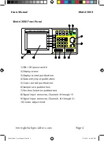
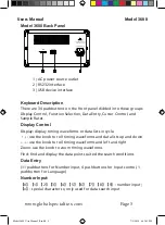
Page 9: ... op R ecal l Save Sour ce Ti m e St at e ay sp l D i Fi nd Zoom 7 4 1 0 x a e g an u g L Shi f t 9 8 5 6 3 2 C ur sor 1 C ur sor 2 R eset 1 ON Off power switch 2 Display screen 3 Display control pushbuttons 4 Data entry input pushbuttons 5 Cursor control pushbuttons 6 Sample rate pushbuttons 7 Function Selection pushbuttons 8 Signal input connector Channels 0 through 15 9 Signal input connector Ch...

Page 10: ...r Control and Sample Rates Display Control Display display timing waveforms or data lists in cycle use the knob to roll timing waveforms and data lists up and down use the knob to roll timing waveforms and left and right Zoom use the knob to zoom timing waveforms Find find and display the data points suited the search conditions Data Entry 11 pushbuttons for Number input 4 pushbuttons for Input co...

Page 11: ...resume the default parameters settings Function Selection Channel select and set the sequence order name color and switch of each channel in cycle Threshold select and set the threshold voltage System select and set the system parameters Trigger select and set the parameters and the switch in the trigger process Time State select the mode of timing sample or state sample in cycle Source select int...

Page 12: ...ss of data the data value in Decimal Dec the data value in Hex the data value in Binary Bin The parameters display frame is below the data lists frame the three parameters on the left are the state parameters which changes automatically with different operations showing the current state of the instrument The 2 parameters on the right are the parameters settings of the system and can be set with n...

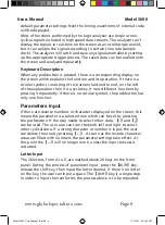
Page 13: ...s different functions by pressing it repeatedly If there is no circular symbol the pushbutton has only one function Parameters Input If there are reverse numbers or characters displayed on the screen this means the parameter is a selected one which can be set by pressing the pushbutton If the user needs to select other data and can be used The user also can turn the knob left and right to select o...

Page 14: ...y to select the channel label setting Set the channel label by using the numeric keys or letter keys Every channel label can be set by the user Channel Color Setting Press Channel key to select the desired channel color setting Set the color using the numeric keys Every channel can be set according to user s choice of color Channel Switch Setting Press the Channel key to select channel switch sett...

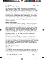
Page 15: ...e input signals are higher or lower than the threshold voltage It doesn t reflect the real amplitude of the input signals and may be far different from the real waveforms of the input signals This kind of waveform displayed by the logic analyzer is usually called a pseudo waveform Sampled Signals In practical operation the sampled signals appear by groups For example grouped by the data bus or the...

Page 16: ... between 5V and 3 3V The setting range of threshold voltages for CMOS is between 5V and 4 3V If the tested signals contain large ringing effects or other voltage noises there will be extraneous data in the sampled results If this happens repeat the sampling function to adjust the threshold voltage and observe the sampling waveforms until clear and correct sampling waveforms are obtained Display Se...

Page 17: ...setting the waveform of sampled stored data block associated with this new window address will be displayed To continuously observe a waveform on the display press and turn the knob The window address will change continuously showing the waveform rolling from left to right in the display window The parameter in the second row on the right bottom of the wave frame is a scroll step function Turn the...

Page 18: ... the time increment that each lattice of scale line represents both in the above and underside two rows of waveform frame The essence of waveform amplification is that a number of sampled data points in memory are displayed continuously The amplified waveform allows dense waveforms to be viewed more clearly This does not generate any distortion to the waveform However waveform amplification is una...

Page 19: ...a memory This allows user to find all the data words conforming to setting conditions from sampled data The find data function runs after finishing the data sampling It is used to look up a data word set randomly in stored sampling data This point is different from the trigger conditions data word that will be described in another section Trigger conditions is preset in advance before sampling and...

Page 20: ...nob a step The cursor moves one point distance on the screen Press 9 then turn the knob a lattice the cursor moves nine points distance on the screen Recommendation is to first move the cursor with a longer step to the desired aim point Then move the cursor with a shorter step to the aim point Cursor Measurement Model 3600 is able to measure the sampling data value of any point in the display wave...

Page 21: ...oints However if the address difference between the two points measured exceeds 280 the two points can t be displayed in the same interface at the same time A different measuring procedure is used Set the cursor1 and the cursor2 into different characteristic modes Cursor1 is a drift cursor appearing in the display window continuously It can be seen as an aim line and is able to move anywhere withi...

Page 22: ...data in memory which requires properly setting the sampling parameters Sampling Mode There are two sampling modes for this logic analyzer One is timing sample which collects samples of the external signals using the internal equal time interval clock The sampled data is equal time interval data in other words it takes time as the independent variable The timing waveforms after sampling will basica...

Page 23: ...e can use the two channels to monitor the adjustment effect Sampling mode can be set with the Time State key inner clock for timing sampling and the external clock for state sampling The external clock contains external clk1 and external clk2 The default setting is the timing sample using the internal clock Clock Limitations To view variations of tested signal a higher sampling velocity should be ...

Page 24: ...and input the clock cycle value with decimalization numbers 0 9 Its unit is ns resolution is 10ns the last number on the right is to be ignored as it has no use The minimum cycle value is 10 ns the maximum value is 999999990ns approximate to 1s When the code generator s clock is changed the waveform s display change is visible The default setting of the clock cycle is 10 ns meaning the highest sam...

Page 25: ...lts displaying continuously When user presses Run Stop again the sampling process stops This is generally used to view a dynamic change of a tested signal or dynamic response of the adjusting parameter setting Once the characteristics of tested signal are analyzed or parameter setting adjust suitably press the single key to sample and analyze the results in detail Trigger Setting In today s modern...

Page 26: ...s the Single key the sampling process does not initially start but first checks the start conditions When it is determined the data in the input signals is a match the sampling process starts immediately The start bit select can be set with numbers in Hex representing 32 input channels If the bit select is set to 0 this indicates this channel is to be ignored It is not involved in the start match ...

Page 27: ...itions to capture the desired signals After the signals are captured and stored the instrument takes a short time of store delay and the sampling process stops automatically The suitable setting of trigger conditions can decrease storage of useless data which improves the effective utilization of the memory The start bit select can be set with numbers in Hex representing 32 input channels If the b...

Page 28: ...e first resets and the count value increments one when it meets the trigger event once This happens until the count value reaches the setting value of the trigger event and the trigger process finishes The trigger events count can be set with numbers in Dec the setting range is 1 999 the default setting of the trigger event count value is 001 Trigger Select The trigger select switch can be set wit...

Page 29: ...y in other words the sampling process stops automatically after sampling 600 clock cycles randomly Manually Stop Sampling Process If the start select switch is disconnected but the start conditions are set unsuitably the sampling process will not start Or if set trigger select switch is disconnected but trigger conditions are set unsuitably the trigger process can not stop Under these two conditio...

Page 30: ... of red data The left line is address value of cursor in Dec the middle line is data value of cursor in Hex and the Bin data value of cursor is on the right line Save Recall Parameter Storage Parameter settings will be different for various measurement applications and just using the default settings may not be adequate To set the parameters each individual time can be time consuming It is recomme...

Page 31: ...is turned on to Model 3600 the instrument first loads the default parameters settings and stores them If the user modifies the parameter settings during a measurement and the data isn t being captured correctly press Reset to recall the default parameters settings for initialization to return the instrument to normal operation Programmable Interface Model 3600 is configures for USB device and RS23...

Page 32: ...tection Maximum input voltage 40 V Sampling Storage Timing Sample Internal clock Sampling Rate 1Hz to 100MHz 10ns to 1s cycle resolution 10ns State Sample External clock clk1 external clock clk2 Sampling rate 1Hz to 35MHz Clock limit External clock clk1 AND clk2 clk1 OR clk2 Sample phase Rising edge Falling edge Sampling objective Internal code generator external signal source Sample control Singl...

Page 33: ...ves rolling 32 Channels vertical rolling display 256K data points horizontal rolling display Lists rolling 256K data rows vertical rolling display Waveform Zoom Horizontal zoom times 1 to 100 scale 1ns div to 4s div Cursor Measure Cursor 1 Floating cursor floats arbitrarily in display screen Does not move with waveforms or lists Measure Cursor 2 Sticking cursor as a reference point affixed on the ...

Page 34: ... 31 channels are used for monitoring external clock clk1 and clk2 Code Rate Frequency 1Hz to 50MHz cycle 20ns to 1s resolution 10ns Operation Options Keyboard operations continuous adjustment knob Power Conditions Voltage AC 100V 240V Frequency 45Hz 65Hz Power 30 VA Environmental Temperature 0 to 40 C 32 F to 104 F Humidity 80 Dimensions 329 283 155 mm 13 2 x 11 3 x 6 2 in Weight 3 kg 6 6 lb Model...

Page 35: ...vent of misuse or abuse of the product or as a result of unauthorized alterations or repairs The warranty is void if the serial number is altered defaced or removed Global Specialties shall not be liable for any consequential damages including without limitation damages resulting from loss of use Some states do not allow limitations of incidental or consequential damages So the above limitation or...

Page 36: ...Return shipping to locations in North American is included for Warranty Service For overnight shipments and non North American shipping fees please contact Global Specialties Include with the returned instrument your complete return shipping address contact name phone number and description of problem Procedure All repairs and or calibrations must have a Return Authorization RMA number prior to se...

Page 37: ...www globalspecialties com Innovative Training Solutions Global Specialties 22820 Savi Ranch Parkway Yorba Linda CA 92887 1 800 572 1028 Model 3600 User Manual_B indd 32 7 2 2010 4 41 48 PM ...

Reviews: