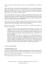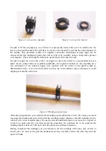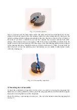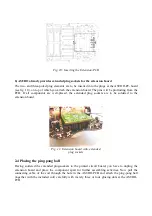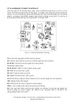
Fig. 13: Completed and placed Extension Board
Note
: Initially the terminals VCCOUT1/2, GNDOUT1/2 and ADC2OUT/ADC3OUT will not be
needed. Additionally to the fixing hole at the PCB, these terminals may later be used to connect two
distance sensors in a triangulation-sensor-system. This will allow the ASURO to apply an
autonomous navigation system and to be searching metallic objects as well.
For more details please consult “More Fun with ASURO, Volume II”. Instead of attaching the
triangulation-sensors directly to the ASURO-PCB, you will now have to attach these to the
extension board.
2.6 Startup procedure
Having attached the ping-pong ball including the coil and having completed the PCB-assembly, you
can now insert the PCB into the (deactivated!) robot. Please check the isolation of the components
carefully: none of the components at the ASURO-PCB are to short-circuit the metallic areas of the
extension board. The coil cabling is to be guided from below the PCB to the side of the screw
terminal CON1 and may now be attached to the screw terminal. In this case the polarity may be
neglected.
In order to view the oscillations in the resonator circuit, you enter the following program
(MinesweeperTest1):
#include "asuro.h"
extern volatile unsigned char count72kHz;
int main(void)
{
unsigned char oscillation;
Init();
DDRD &= ~(1<<2); // Change Port D Pin 2 to input
StatusLED(OFF);
while(1)
{
count72kHz=0;
oscillation = FALSE;


