Attention: If ASURO has not been prepared for assembling an extension PC-board, you will have to
postpone attaching the ping-pong ball until the preparation for the extension board has been
completed.
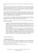
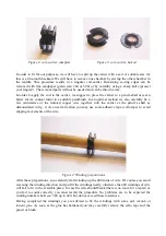
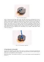
Fig. 9: Coil - attached to the ping-pong ball
2.3 Inserting the extended plug sockets
Before assembling the components to the PC-board you will have to insert the extended plug
sockets. You will have to use a different procedure depending on the status of the ASURO-system.
Please check whether the ASURO has been prepared for assembling an extension PC-board or not.
a) ASURO does not provide extended plug sockets for the extension board
In this case you will have to remove the components for the line-tracing (the photo-transistors T9
and T10, as well as the LED D11) from the PC-board. These activities require a removal of the
ping-pong ball.
The easiest way to proceed is to heat the components, which are to be removed with
a soldering device while simultaneously and carefully pulling the components out of the PC-board's
holes. If you are lucky the PCB-holes are free, otherwise the superfluous solder may carefully be
removed with a solder sucker and / or a solder wick.
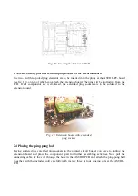
Now the two- and three-poled male and female plug elements have to be assembled and –
additionally to the plugs at the ASURO-board – inserted in the ASURO-PCB as illustrated in fig.
10. In a following step you
first
insert the extension board and
at last
solder the male and female
plug elements at the extension-board and the ASURO-main PC-board.
Test Equipment Depot - 800.517.8431 - 99 Washington Street Melrose, MA 02176


