- 17 -
This code shows that the system calls a few functions in Battery ()
e.g. in order to measure the battery voltage. This function supplies a
value between 0 and 255 that is processed in the PC program and
displayed on the terminal. The bytes 10 to 13 are free and can be
freely programmed.
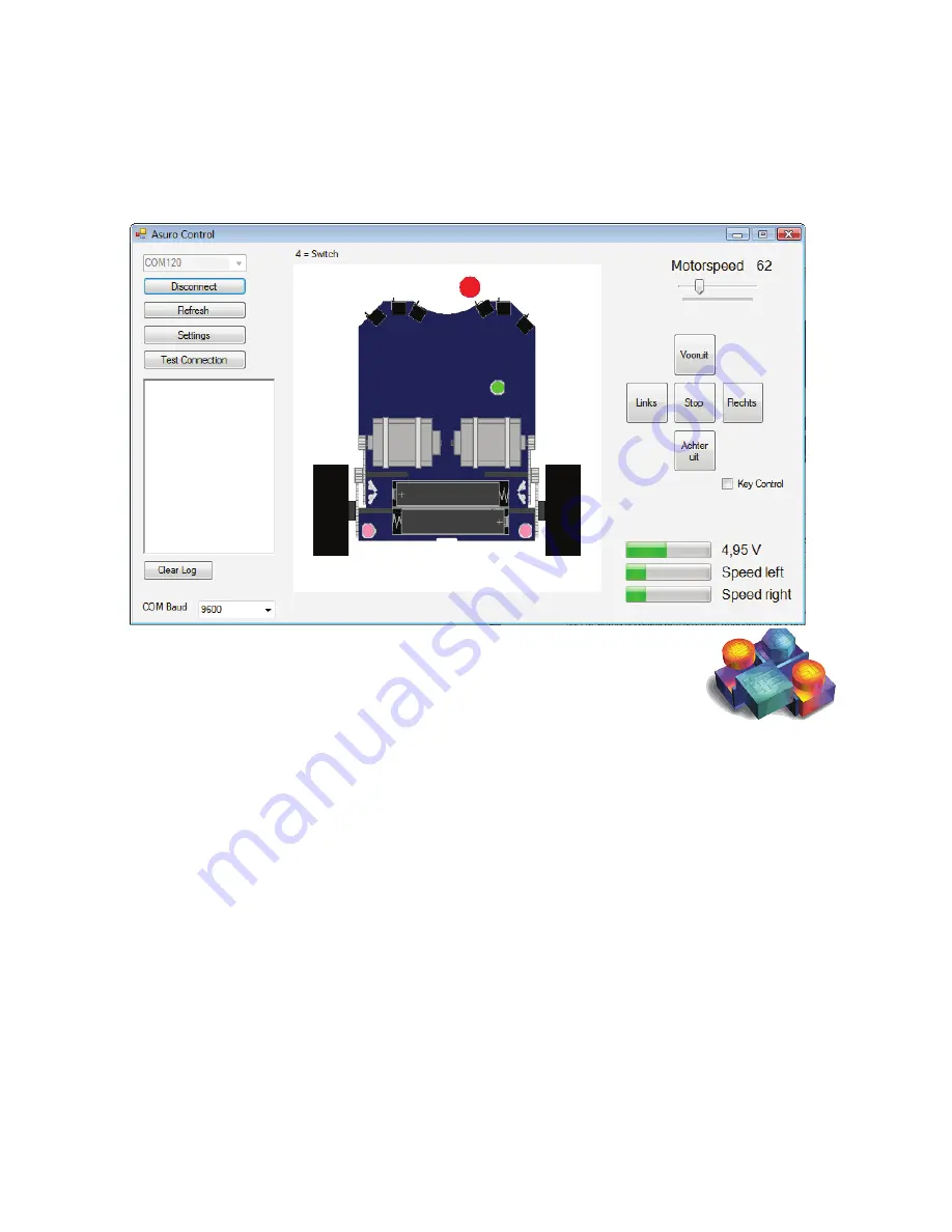
Once the application ‘ASURO CONTROL’ has been started, the pro
-
gram displays the screen above. Now you can get in contact with
ASURO and control the robot. The WT dongle must be connected to the
PC. When the WT dongle is connected, a click on the ‘Refresh’ function
triggers a request to all connected COM ports.
Once you have selected the correct COM port for the WT dongle, the
connection will be established by clicking on the ‘Connect’ function on
the ASURO control screen. This command triggers the link between the
WT dongle and the ‘ASURO Control’.
Consequently the motor speed and the battery voltage will be display-
ed in the bottom right corner of the screen. As soon as a switch on the
front panel of the robot is activated, the program marks this switch
as a red dot. This way the program shows a collision on the ‘ASURO
Control’ display. The program display of the application shows also
the colo
r
change of the ASURO LEDs.
Fig. 13 : Asuro Control Software (Visual Basic)
Summary of Contents for ARX-WRL
Page 1: ......
Page 2: ... 2013 Global Specialties ...
Page 6: ......
Page 8: ......
Page 16: ......
Page 31: ... 31 APPENDIX ...
Page 33: ... 33 A RP6v2 USB Programmer WT DONGLE ...
Page 34: ......


