background image

PB-203A

Revision: 2/2012

Powered Proto-Board


Instruction Manual 

www.

GlobalTestSupply

.com

Find Quality Products Online at:

sales@GlobalTestSupply.com

Summary of Contents for PB-203A

Page 1: ...PB 203A Revision 2 2012 Powered Proto Board Instruction Manual www GlobalTestSupply com Find Quality Products Online at sales GlobalTestSupply com...

Page 2: ...www GlobalTestSupply com Find Quality Products Online at sales GlobalTestSupply com...

Page 3: ...g area the PB 203A is ideally suited for virtually any type of breadboarding circuitry from TTL CMOS and ECL to op amps audio comparators video amps microprocessor components phase locks and more Use...

Page 4: ...ctions appropriate for a variety of educational levels and course goals The central concept upon which we base our entire product line is education through application We believe that relevant scienti...

Page 5: ...Instructions page 7 Power Supply Description Schematic Diagram page 9 Using the PB 203A page 10 Breadboarding Techniques page 12 Service Warranty Information page 13 www GlobalTestSupply com Find Qua...

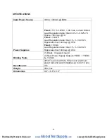
Page 6: ...le less that 10mVp p 0 5A Fixed 15VDC Load Regulation better than 1 0 04 C Ripple less that 10mVp p 0 5A Binding Posts 1 Black Chassis Ground 3 Red Power Supply Outputs 5VDC 15VDC 15VDC Breadboards 22...

Page 7: ...s be stripped 1 2 to 3 8 from each end to ensure easy insertion into the solderless breadboards After you ve built up a few circuits you ll have a good collection of pre stripped jumper wires Pre form...

Page 8: ...op and bottom case halves can now come apart d Remove the screws holding the sockets to the top cover e Unsnap the sockets Remove the vinyl label from the socket containing the broken wire a heat gun...

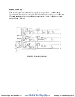
Page 9: ...ator This circuit provides the plus and minus 15 Volt rail voltages as well as the 5V supply available for use in breadboard experiments Figure 2 shows the circuit diagram of the PB 203A FIGURE 2 Sche...

Page 10: ...ated even a short length of power bus can cause a linear IC to break into oscillation at high frequencies due to increased inductance This increased inductance can be offset by adding simple by pass c...

Page 11: ...GND 5V 15V 15V 30V 20V 15V 15V 5V FIGURE 3 Power Supply Combinations www GlobalTestSupply com Find Quality Products Online at sales GlobalTestSupply com...

Page 12: ...e from the leads of the components Placing a formerly taped component into a socket connector may result in a poor electrical connection and worse still leave tape adhesive in the socket Avoid this pr...

Page 13: ...scontinue models change specifications price or design of this device at any time without notice and without incurring any obligation whatsoever The purchaser agrees to assume all liabilities for any...

Reviews: