15
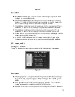
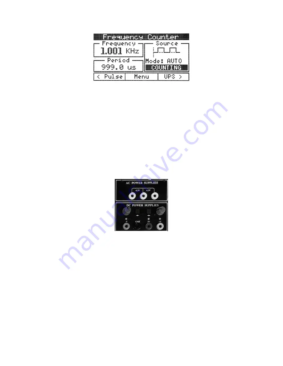
Figure 6
The following information is displayed in the counter panel:
•
The measured frequency and the corresponding period
•
The type of the input signal
•
Counter mode: AUTO or MAN
•
The current state of the counter: NO SIGNAL or COUNTING.
6.4 DC Power supplies
Front-panel controls
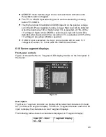
Figure 7
shows the DC Power Supplies controls on the front panel of the trainer.
Figure 7
Positive voltage knob:
changes
the
value of the +V DC power supply between
0V and 20V.
Negative voltage knob:
changes
the
value of the -V DC power supply between -
20V and 0V.
buttons:
move the cursor from one digit to another inside a field or to the
next field.
Display Area and Screen Interface
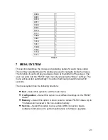
Figure 8
shows the trainer’s screen displaying the DC power supplies panel.


