34
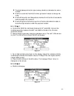
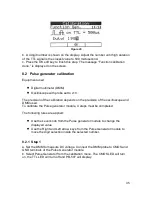
b. Two 4 digit numbers are shown on the display. Adjust the numbers until the
oscilloscope indicates the closest value to 1.0Vpp of the square signal and the
closest offset to zero.
c. Press the OK soft key to finish this step. The message “Step 7 done.” is
displayed on the screen.
8.1.8 Step 8
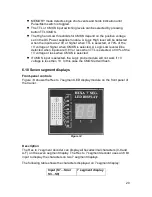
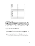
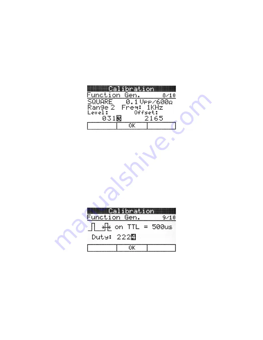
a. PB-507 will display:
Figure 24
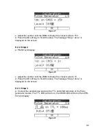
b. Two 4 digit numbers are shown on the display. Adjust the numbers until the
oscilloscope indicates the closest value to 0.1Vpp of the square signal and the
closest offset to zero.
c. Press the OK soft key to finish this step. The message “Step 8 done.” is
displayed on the screen.
8.1.9 Step 9
a. Connect the oscilloscope probe to the TTL and GND terminals of the Function
generator module.
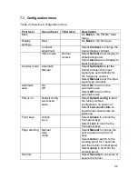
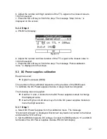
b. The OUT and TTL LED will turn on and PB-507 will display:
Figure 25
c. A 4 digit number is shown on the display. Adjust the number until high duration
of the TTL signal is the closest value to 500 microsecond.
d. Press the OK soft key to finish this step. The message “Step 9 done.” is
displayed on the screen.
8.1.10
Step 10
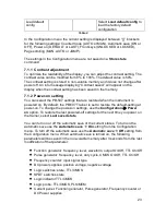
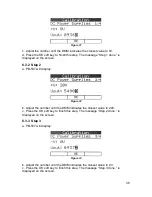
a. PB-507 will display:

