RP6 ROBOT SYSTEM - 3. Hardware and Software Setup
The mainboard may now be put back onto the chassis. Move any cables between
mainboard and plastic division bars or other chassis parts away by using your finger
or a long screwdriver, in order to
locate the mainboard flat and even on the
chassis!
Before fixing it again, please check for any cabling collisions between main-
board, chassis and gear-wheels! Now you may fix the main board by tightening the
four screws – and we're done!
3.7. Charging the Batteries
If you did not install charged batteries already as we recommended it, you will now
have to attach an external charger. Please turn the main power switch into position
“OFF” for charging! Battery charging only works if the Robot is turned off. The main
switch connects the batteries either to the RP6's electronics or to the charger connect-
or.
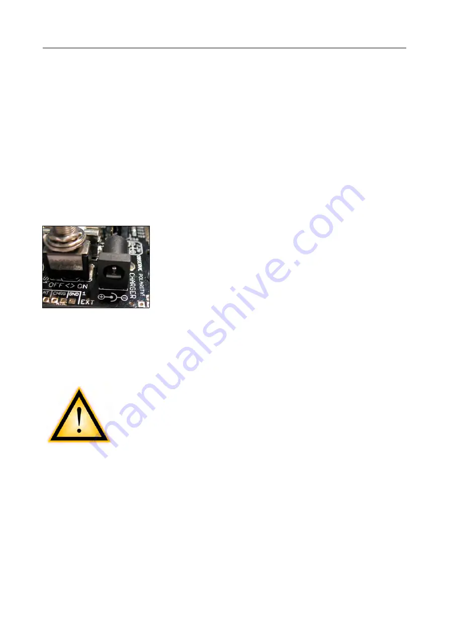
Check the polarity of the charger compared to the charging supply plug (labelled
“Charger”) located next to the robot's main power switch!
You can see a polarity marking on the mainboard in front of
the plug (see figure).
The negative terminal is located
on the OUTER METAL PLATE and the positive terminal
on the INNER pin!
Charging time depends on the used charger and the batter-
ies (Microprocessor controlled devices, e.g. Smart Charger
1A / 2A fast charger will
need between 2 and 3 hours, standard chargers
require about 14 hours of charging time) – please read the details in the manual of
the charging device!
Do not turn the robot's main power on while charging is in progress! Remove
the charger before switching the robot on!
3.8. The first test
ATTENTION! Please read this and the following setion com-
pletely before perfoming the test!
If anything different from the following description happens,
you should turn off the robot
immediately
and note exactly
what went wrong! If the chapter “Troubleshooting” does not
provide an answer, you may contact the support!
OK – ready to go! Turn the robot on! The two red status LEDs in the middle should
light up. After a small delay they turn off, one of the other red LEDs (SL6) starts blink-
ing and one of the green LEDs (SL1) is illuminated permanently. This indicates the ab-
sence of a user program in the controller's memory. If a user program is in the
memory, only the green Status LED SL1 will be blinking (this can be the case if the
test program has not been deleted in Facotry – and no, this is not a problem).
The yellow PWRON LED should light up for about one second after turning the robot
on – it saves energy to deactivate most sensors, e.g. the encoders.
After approx. 30 seconds, the red blinking LED SL6 and all other LEDs will turn off.
The robot's microcontroller will automatically switch to standby mode as there is no
- 43 -


