background image

From the library of Superior Sewing Machine & Supply LLC - www.supsew.com

Summary of Contents for WF 926-SNB

Page 1: ...GLOBAL WF 926 SNB AUT Instruction Parts Manual www globalsew com info globalsew com ...

Page 2: ...From the library of Superior Sewing Machine Supply LLC www supsew com ...

Page 3: ...bin 4 7 Threading ofbobbin thread 5 8 Tension adjustment ofbobbin threads 5 9 Balance of thread tension 5 10 Needle thread tension 5 11 Adjustment ofpressure of presser foot 5 12 Timing between rotating hook motion and needle motion 6 13 Adjustment ofFeed dog height 6 14 Adjustment the needle stop position 6 15 Needle bar stop position left right 7 16 Walking foot and presser foot vertical stroke ...

Page 4: ...e 12 Parts Catalog A ARM BED MECHANISM 13 B THREAD TENSION REGULATOR MECHANISM 16 C ARM SHAFT LOWER SHAFT MECHANISM 20 D PRESSER FOOT MECHANISM 22 E NEEDLE BAR TAKE UP LEVER MECHANISM 25 F TOP FEED ROCK SHAFT MECHANISM 28 G LOWER SHAFT FEED ROCK SHAFT MECHANISM O H HOOK SADDLE MECHANISM 33 I KNIFT MECHANISM 1 35 J KNIFT MECHANISM 2 37 K TOUCH BACK AND DETECTOR MECHANISM 49 L OIL LUBRICATION MECHAN...

Page 5: ...d capacity will be exceeded It may cause transformer winding burned out C Rotary direction It is possible to change the rotary direction ofthe motor by removing the rubber cap from the bottom left side of the front cover on the control box and push the internal direction selector switch The built in lamp in the internal switch is off when the motor is rotating counterclockwise as facing to the mot...

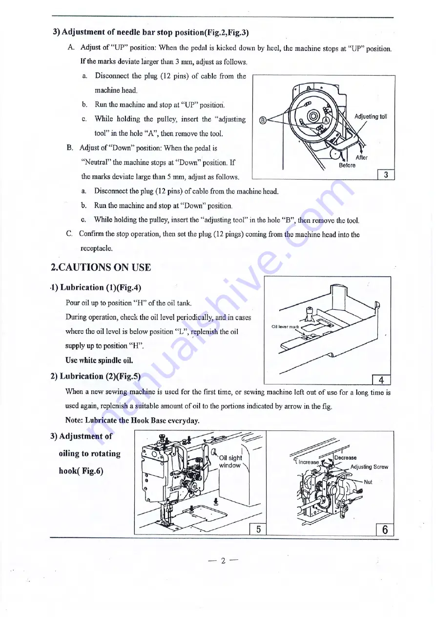
Page 6: ...ile holding the pulley insert the adjusting tool in the hole B then remove the tool C Confinn the stop operation then set the plug 12 pings coming from the machine head into the receptacle 2 CAUTIONS ON USE 1 Lubrication l Fig 4 Pour oil up to position H ofthe oil tank During operation check the oil level periodically and in cases where the oil level is below position L eplenish the oil supply up ...

Page 7: ...to attach needle Fig 7 Note Before attach needle be sure to turn offthe power Loosen the needle clamping screw Hold the needles so that the two needles side with the long grooved faces each other and insert it as deeply as it will go into the needle clamping holes tighten screws 2 _ How to wind the lower thread Fig 8 Strengthofwinding Particularly in the case ofnylon or polyester thread wind the b...

Page 8: ...h thread guide B as show in Fig 10 B With the take up lever located at the upper most position pass each thread in the order in Fig 11 Note Pressing the upper thread kJsening button the upper thread can be pulled out easily Needle thread tension releasing button Lead the Lead the thread thread lertword rtghtward Fig IO Fig 11 5 Adjustment ofstitch length and reverse sewing Fig 12 A Rotate the stit...

Page 9: ...ckward 8 Tension adjustment ofbobbin threads Fig 15 9 Balance of thread tension Fig 16 l0 Needle thread tension Fig 17 Needle thread tension should be adjusted in reference to bobbin thr lad tension To adjust needle thread tension tum each tension adjusting nut Needle thread tension can be also adjusted for special fabric and thread by changing intensity and movable range ofslack thread adjusting ...

Page 10: ...g is too low or pressure ofpresser foot is too small C Feed dog height should be measured at the point where the needle is at the top position 0 6mm ii n For light fabric Approx 0 8mm For usual fabric Approx 1 0mm For heavy fabric Approx 1 2mm Adjustment procedure A Lay down the machine bed toward the otherside 1 0mm 1 2mm Z71 IFig 20 B Turn the balance wheel by hand stop when the feed dog is rais...

Page 11: ... tighten the special nut Special boll Crank Crankrod The vertical strokes ofpresser feet can be adjusted within a range from 2mm to 6mm 17 Relationship between rotating hook motion and take up lever motion Fig 24 Fig 22 When the timing belt toothed belt was removed for its replacement for example the relationship between rotating hook motion and take up lever motion should be adjusted as follows A...

Page 12: ... and B Fig 27 E Check that the right feed lifting rockshaft crank is connected with the link at right angle as shown in Figure F If the connection is not at right angle remove the back cover loosen screw C and move the right link to connect B the right feed lifting rock shaft with the link at right angle Fig 28 Feed lifting rock shaftcrank middle G After the completion ofadjustment fully tighten t...

Page 13: ... but tum the balance wheel more finnly _ r c Release the push button the safety clutch device low Shaft Eccentric Pin is set C Force applied to the safety clutch Fig 30 Fig 30 a The force applied to the safety clutch is the smallest when the mark of eci entric pin faces the center ofthe lower shaft The force proportionally increases as the mark faces the outside b To adjust the force slide the tim...

Page 14: ...byhand until needle reaches the Lowest position b With the needle at the lowest position depress cam follower crank turn the balance wheel until the movable knife reaches the extremity ofits stroke c Manually rotate the inner hook in the direction indicated by arrow in Figure and adjust gap between the movable knife and the inner hook stopper to about 0 5 mm the screws A and B should be loosened f...

Page 15: ...rtion of thread release cam as shown in Fig To adjust loosen the screws C and draw the wrre F Make fine adjustment by loosening the nut D G Loosen the nut D and make the outer casing approach rightward to increase the opening value Thread rele e c11m I Thread trimmer cam ScrewC Whae park point Nut D 25 Adjustment ofscissoring pressure of movable knife and fixed knife Fig 35 A Loosen the fixed knif...

Page 16: ...ntact the rocking cranks C and D to the stopper pins E and F and tighten the connecting link clamp bolt J H Turn the balance wheel by band until the needles reach the lowest position I Loosen the nuts G and H CnnnP r liOU link Hook brack 31 latt Cam groove J_ hase Screw A Screws Fig 36 Fig 37 J Depress the cam follower crank K and adjust the connecting rod L so that the cam roller can smoothly ent...

Page 17: ...SPARE PARTS LIST Global International BV H Figeeweg 4 2031 BJ Haarlem tel 023 5319584 fax 023 531 1022 e mail global imca net Global Parts bv H Figeeweg 48 2031 BJ Haarlem tel 023 5425312 fax 023 5423422 e mail globalparts planet nl From the library of Superior Sewing Machine Supply LLC www supsew com ...

Page 18: ...A ARM BED MECH ANISM 2 3 4 2 5 6 8 9 10 11 40 39 38 37 36 35 33 34 33 32 31 30 29 15 14 13 12 13 From the library of Superior Sewing Machine Supply LLC www supsew com ...

Page 19: ...000D2160 Screw 1 1 SM9 64 40 X4 5 Al9 H4726B8001 1bread guide 1 1 A20 H0213B8001 Face plate 1 1 A21 H2400B2080 Screw 2 2 SM3 l6 28 xl2 l A22 H2400B2070 1bread guid 1 I A23 H0212B8001 Shaft supporter I I A24 H2400B2060 Spacer I 1 A25 H3200B2060 Oil guide plate I I A26 HA7311C606 Screw 2 2 SM11 64 40 xI5 A27 8602030200 Pin 2 2 A A28 HA100B21 IO Screw 2 2 SMll 64 40 x5 5 A29 H3219B0067 Slide plate co...

Page 20: ...A ARM BED MECHANISM 2 3 4 2 5 6 8 9 10 25 11 40 39 38 37 36 35 3 34 33 32 31 30 29 15 14 13 12 13 From the library of Superior Sewing Machine Supply LLC www supsew com ...

Page 21: ...A ARM BED MECHANISM Fig Part No Description No A40 H4746B8001 Slide plate lefl I 15 z VJ I D s I C0 a 1 2 V I 1 Remarks _ b _ 1 From the library of Superior Sewing Machine Supply LLC www supsew com ...

Page 22: ...OR M ECHANISM 1 2 3 4 5 6 7 8 9 10 11 12 13 14 15 16 17 18 20 21 22 48 47 46 45 44 43 42 41 40 39 38 37 36 35 16 23 p 1 24 d 2s 34 33 32 31 30 26 27 28 29 From the library of Superior Sewing Machine Supply LLC www supsew com ...

Page 23: ...06B0676 Screw 1 I SM9 64 40 x6 B21 83306B0661 Thread guide I 1 822 HA31080702 Tension releasing disc 2 2 823 f 1471OC8001 Spring 2 2 824 HA115B7010 Thumb nut revolution stopper 2 2 825 HA310B0701 Thumb nut 2 2 B26 HA310B0705 Thread tension disc 4 4 827 83221B6816 Pin I 1 828 H322IB0689 Thread tension stud I I SMl 4 40 X23 829 83221B0686 Thread tension stud 1 l SMl 4 40 x23 830 8324818721 Thumb nut...

Page 24: ...B NEEDLE BAR CONTROL MECHANISM 81 80 79 49 50 51 52 53 54 11 b 78 77 76 75 74 73 72 71 70 69 68 67 66 65 64 63 62 61 60 17 58 59 From the library of Superior Sewing Machine Supply LLC www supsew com ...

Page 25: ...3 3 SM15 64 28 xS 5 Cl2 H3205Cl021 Pulley 1 1 C13 HA100F2130 Screw I I SMl5 64 28 xl4 5 Cl4 H3205J0662 Bearing l 1 Cl 5 H3205J066 Collar I 1 Cl 6 HAIIOD0672 Screw 2 SMI5 64 28 x12 Cl7 H4IOOC2040 Pulley 1 C 8 H3200C2030 Cog belt I I c 19 HA104F0654 Screw I I SM15 64 28 xtO C20 H4713D8001 Link I I C21 H4714D8001 Pin I I C22 H4716D8001 Spring 1 I c23 H007013025 E type ring 1 l C24 H4717D8001 Link I I...

Page 26: ...SSER FOOT MECHANISM 58 1 2 3 Cj 4 2 5 6 7 8 9 10 1f 12 13 14 55 4 54 46 oiil 45 44 P 43 42 41 40 39 38 37 3029 G 59 32 31 60 61 62 22 18 From the library of Superior Sewing Machine Supply LLC www supsew com ...

Page 27: ...C ARM SHAFT LOWER SHAFT MECHANISM 4 5 6 7 8 9 10 11 12 13 14 20 r 18 19 20 u 23 I PW J 24 25 10 30 29 28 27 26 From the library of Superior Sewing Machine Supply LLC www supsew com ...

Page 28: ... B57 HA7311C606 Screw I I SM11 64 4Q xI5 B58 H3400D2060 Cannulation I 1 L 7 7 B59 H3407D0671 Pin 1 I B60 H3408D0681 Pin 1 1 B61 H3408D0682 Spring I I B62 H3408D0686 Tension bracket I I B63 H0210C8001 Screw I I SM l 64 40 x22 B64 H007013040 E typc ring I I GBff896 4 B65 H3408D0684 Lever I I B66 H3408D0685 Pin 1 I B67 H3400D2100 Spring I J B68 HA300C2030 Screw 2 2 SM l 64 40 x8 B69 H0208C8001 Plate ...

Page 29: ...8001 Collar I I D20 H4742E8001 Screw I I SM 1 64 40 xs 5 D21 H3100G2170 Screw I I SMI 4 24 xJ7 D22 H4730E8001 Lever spring I I D23 H4729E8001 Screw I I SMIS 64 28 x79 D24 H4727E8001 Twist spring I 1 D25 H4728E8001 Knee lifting lever 1 1 D26 H3100G2130 Screw I I SMl 4 24 x7 D27 H4726E8001 Nut 1 I D28 H4725E8001 Screw I I SMl 4 24 xt9 D29 HAI I1G0683 Screw 2 2 SM l 64 40 xt2 D30 H4723E8001 Guide I I...

Page 30: ...R FOOT MECHANISM 58 57 t 56 1 55 4 4 154 46 oiil 45 44 43 42 41 40 39 38 37 2 3 4 2 5 6 7 8 9 10 11 12 13 14 3029 tr 59 32 31 60 61 62 22 18 From the library of Superior Sewing Machine Supply LLC www supsew com ...

Page 31: ...TAKE UP LEVER MECHANISM 35 36 37 fj 38lJ 39 fj 40 t 41 1 44 45 t 46 t I 49 50 29 58 I 5 7 51 72 73 52 5 6 7 10 11 12 13 2322 21 65 59 60 25 66 0 From the library of Superior Sewing Machine Supply LLC www supsew com ...

Page 32: ...M l 64 40 x17 5 D51 H4708D8001 Set screw 2 2 SMl 4 24 xJ3 D52 HE504D8001 Lifting presser I 1 5 16 D52 HE304E8001 Lifting presser I I 3 8 D53 HE013N8001 Finger gusrd I 1 D54 H0205E8001 Bushing I 1 D55 H3210F0681 Screw I 1 M5x6 D56 HE510D8001 Bushing I 1 D57 HE51ID8001 Cover I 1 D58 HE106F8001 Screw 2 2 SMl 8 44 x6 D59 HE512D8001 Screw I 1 D60 HE507D8001 Crank I I D61 H4708D8001 Screw I 1 SM1 4 24 X...

Page 33: ... 1 1 8 19 H3410C301K Screw I 1 SM9 64 40 X6 5 820 HE523E8001 Guide plate 1 I 821 HA7121N304 Screw I 1 E22 H3410C301C Screw 1 1 SM3 32 56 x4 2 E23 H34 0C301B Needle bar supporter 1 1 E24 H3410C3019 Screw 1 1 SM9 64 40 x3 5 E25 H34IOC3018 Needle bar holding stopper I I E26 H3410C3017 Needle bar holder 1 1 E27 H3204D6513 Felt I 1 828 H3410C3014 Needle bar holder 1 I 829 HE505E8001 Needle bar rock fra...

Page 34: ...AKE UP LEVER MECHANISM 35 36 37 fj 38 1 39 fj 40 f 41 1 44 45 r 45 48 4 7 49 so 29 58 51 57 7 llllt 54 53 72 73 5 6 7 59 60 52 25 10 11 12 13 66 0 From the library of Superior Sewing Machine Supply LLC www supsew com ...

Page 35: ... H0206F8001 Vibrating presser bar link I 1 E57 H3100F2060 Spring I I E58 I IE50607101 Vibrating presser spring guide I I E59 H3410C301P Square block I I E60 H3406C0671 Screw I I SMl5 64 28 x10 E61 H3406C0672 Needle bar vibrating crank lefl I I E62 H3400C2050 Washer I I E63 H3204B0652 Bushing 2 2 E64 8602040200 Taper pin 1 I GB Tl 17 4X20 E65 H4736F8001 Needle bar vibrating shall I I E66 H3231 ID50...

Page 36: ...F TOP FEED ROCK SHAFT MECHANISM 37 9 36 l 35 2 3 4 6 34 33 32 31 30 29 28 26 28 13 1 4 1 5 0 ti 1 t 11 25 24 23 22 21 20 19 18 From the library of Superior Sewing Machine Supply LLC www supsew com ...

Page 37: ...uide plate I Fl5 HA300C2030 Screw l SMll 64 40 xg F16 H3200F2110 Spring I I F17 HA700F2030 Pin 1 I FIS HA720F0686 Screw I I SM3 16 28 x 8 F 9 HA720F0685 Bushing I I F20 H49 0O800 Stitch length indicating plate I 1 F21 HA7421Fl20 Dial I l F22 I IA720F0683 Stopper pin releasing lever I l F23 HA720F0687 Coil spring I I F24 HAI09F0671 Screw bar I I F25 HA109F0674 O ring I I F l6 H3206F0662 Pin I I F27...

Page 38: ...AFT MECHANISM 1 2 3 55 56 57 4 5 58 J 53 54 43 42 13 f4 15 f8 19 20 21 22 23 6 7 L 4959 47 46 3 38 37 36 27 28 29 45 44 41 30 33 32 41 40 35 34 33 32 31 30 30 From the library of Superior Sewing Machine Supply LLC www supsew com ...

Page 39: ...M1 4 40 x5 022 H4723H800I Ball bearing 1 I 023 H4727H8001 Bearing holder I I 024 HA731IC306 Screw 3 3 SM9 64 40 X7 025 H4728H8001 Washer I I 026 H4729H8001 Screw I I M6 027 H003058060 Nut I I OB52008M6 028 H473 H8001 Feed connection crank right I I 029 H2012N0652 Screw 1 I SMl 4 24 X 6 030 HA100O2120 Feed rock shaft bushing 2 2 031 H4708D8001 Screw 2 2 SMl 4 24 Xl 3 032 HA10800661 Collar 2 2 033 H...

Page 40: ...HANISM 1 2 3 55 56 57 4 5 Ii 53 54 43 42 11 12 13 14 15 18 19 20 21 22 23 6 7 50 49 59 47 46 37 39 38 37 36 27 25 26 29 45 44 41 30 33 32 41 40 35 34 33 32 31 30 30 From the library of Superior Sewing Machine Supply LLC www supsew com ...

Page 41: ...d bar I 051 H3200H2040 Screw 1 I SM15 64 28 x17 052 H2013J0065 Washer I I 053 H003002030 Nut I I 0Bff6170 M3 054 H429030140 Screw I I oBm8 M3xt4 G55 H3205H0653 Screw I I SMl 8 44 x4 G56 H3205H0652 Felt I I G57 H4743H8001 Feed bar forked connection I I 058 H4748H8001 Feed dog I 5 16 058 H4749H8001 Feed dog 1 3 8 058 H4948H8001 Feed dog I 5116 058 H4949H8001 Feed dog I 3 8 059 H007009070 C tY Pe sto...

Page 42: ...H HOOK SADDLE MECHANISM 3 2 1 33 21 22 23 24 _ _ 25 26 27 28 29 From the library of Superior Sewing Machine Supply LLC www supsew com ...

Page 43: ...bbin case opener holder 2 2 Hl3 H2004J0067 Screw 2 2 SM9 64 40 X7 Hl4 H3200I2030 Washer 2 2 Hl5 H3305I0066 Opener 2 2 Hl6 H005008050 Spring washer 2 2 GB f93 5 Hl7 HA10400658 Nut 2 2 SM3 16 32 Hl8 H33121I204 I Spacer 2 2 Hl9 H33121Il04 Hook shaft bushing upper 2 2 H20 H3204I0657 Screw 2 2 SM3 l6 28 x14 5 H21 H4705I8001 Gear small 2 2 H22 HAI05D0662 Screw 6 6 SMl 4 40 X4 H23 H470618001 Gear large 2...

Page 44: ...I K NIFE M ECH ANISM 1 3 2 _ I I J _ 1 15 14 11 13 11 14 15 11 9 6 35 ...

Page 45: ...SM9 64 40 x4 l07 H491JJ8001 Moved knife 2 08 H4912J8001 Screw 2 SMI 8 44 X9 2 09 H4913J8001 Screw 2 SM9 64 40 X4 5 110 H4914J8001 Spring plate 2 I1 I H4915J8001 Screw 6 SM3 32 56 X3 8 112 H4916J8001 Reversing spring 2 113 H4917J8001 Guide 1 114 H4920J8001 Roller 2 115 H4921J8001 Lever 2 116 H4922J8001 Cover 1 117 H4923J8001 Guide right l II8 H4924J8001 Knife pad right I Il9 H4925J8001 Screw 1 SM9 ...

Page 46: ...KNIFE MECHANISM 2 J 36 37 3S 19 8 9 10 f 21 24 3 25 22 6 7 i i 46 142 23 39 47 48 49 61 72 64 37 50 52 2 7 56 63 51 ...

Page 47: ...7 H003002050 Nut 2 GB f6170 M5 J18 HA300C2030 Screw 1 SMl 1 64 40 x7 J19 H4908K8001 Arm I 120 H4907K8001 Bolt I SMIS 64 28 x12 5 121 H4906K8001 Link I J22 H4905K8001 Screw 2 M5 0 5 x7 5 J23 HAIOOH2080 Pin type I 124 H4946K7101 1bread releasing lever 1 125 H4943K8001 Spring I J26 H4951K8001 Nut 1 SM 1 64 40 J27 H4954K8001 Nut 1 SM3 16 28 128 H4956K8001 Screw 2 SMl 8 44 x7 129 H4955K8001 Bushing I J...

Page 48: ...MECHANISM 2 J KNIFE _ ___ ___ 36 37 38 8 9 10 24 23 25 6 7 16 17 18 15 f __ 33 30 23 39 O4142 i 7 48 49 t 34 3 5 4 61 67 66 65 64 37 50 52 2 57 56 63 51 ...

Page 49: ... Screw I SMl 4 24 xJ6 55 H4983K8001 Screw I SMl 4 24 xt3 J56 H4967K8001 Screw 3 SMl 1 64 40 X7 51 H4966K8001 Stopper 1 158 H4981K8001 Holder I 159 H003008050 Nut 2 GB 1 6172 1 MS J60 H4977K8001 Mounting plate I 161 H4980K8001 Holder 2 J62 H4965K8001 Set plate I J63 H3700B2080 Pin type I J64 H4969K8001 Screw I SM11 64 40 x8 5 J65 H4970K8001 Screw I SM 1 64 40 X6 66 H4971K8001 Lever I J67 H4972K8001...

Page 50: ...K TOUCH BACK AND DETECTOR MECHANISM 2 3 4 6 7 8 9 10 11 12 24 33 32 31 30 40 ...

Page 51: ... 2 SMl5 64 28 xJ2 Kl4 H4931L8001 Pulley complete 1 K15 HA703R0067 Washer 1 Kl6 HA703R0065 Detector bracket complete I Kl7 HA341 D308 Screw I SM15 64 28 x7 K18 H4936L8001 Lever I K19 HAI13F0684 Screw 1 SMl5 64 28 x7 5 K20 H4937L8001 Screw I SM15 64 28 X6 K21 H4938L8001 Rubber ring I K22 H4939L8001 Spring I K23 H4940L8001 Nut 2 K24 H4941L8001 Screw 2 SM15 64 28 xt4 K25 H4942L8001 Nut l K26 H4943L800...

Page 52: ...L OIL LUBRICATION MECHANISM 1 23 4 5 6 7 8 9 10 f 11 12 13 r r 32 181716 15 14 19 37 10 36 15 42 ...

Page 53: ...H3215K0696 Oil pipe I I L19 HI 10012070 Pin I I L20 Hl 10012090 Spring I I L21 HI 10012110 Spring holder I 1 L22 H3204D6510 Screw I I SMl 8 44 x4 5 L23 H3215K0693 Screw J I SM9 64 40 xs L24 H3215K0692 Filter I I L25 H3215K0694 Screw I I SM9 64 40 x7 L26 H47 18J7101 Mounting plate complete I I L27 H3215K0695 Holder l I L28 H3200K0170 Holder I 1 L29 HA731 ICC06 Screw I I SM9 64 40 X6 5 L30 H3210K067...

Page 54: ...L OIL LUBRICATION MECHANISM 45 1 23 4 5 6 7 8 9 10 f 11 12 13 r 32 18 17 16 15 14 19 37 10 36 15 34 15 27 26 25 24 23 22 21 42 ...

Page 55: ...L OIL LUBRICATION MECHANISM z l en Fig I 0 Part No Description Remarks No M l al OI rl L45 HA300C2030 Screw I 1 44 ...

Page 56: ...M ACCESSORIES 1 3 P 10 19 17 14 4 2 28 29 41 40 39 38 37 36 35 34 33 45 ...

Page 57: ... Cotton stand 1 1 Ml 9 H3300L0040 Bobbin winder 1 1 M20 H200800068 Belt cover l M21 HA300C2110 Screw 2 SMl 1 64 40 x8 M22 HA300J2280 Screw 2 2 SM11 64 28 x8 M23 HA300J22S0 Screw I M4X8 M24 H240SK6601 Belt cover complete 1 M24 H49S3N7101 Belt cover compl ete 1 M2S H003008040 Nut 1 GB f6172 1 M4 M26 HA305J0665 Belt cover 1 I M27 HAI00J2120 Magnet block for reservoir 1 l M28 HA307J0067 Hinge complete...

Page 58: ......

Reviews: