background image

From the library of Superior Sewing Machine & Supply LLC - www.supsew.com

Summary of Contents for WF 9995-H

Page 1: ...GLOBAL WF 9995 H Instruction parts manual www globalsew com info globalsew com ...

Page 2: ...From the library of Superior Sewing Machine Supply LLC www supsew com ...

Page 3: ...eedle thread and bobbin thread 8 21 Timing adjustment between the needle and the rotating hook 9 22 lllStalling and removing rotating l1ook 10 23 II1Stalling feed dog 10 24 Feed dog horizontal adjustn1ent 11 25 Stitch lengtl1 error adjustment 11 26 Feed timing adjustn1ent 12 27 Adjusting tl1e tension releasing 111ecl1anisn1 13 28 Upper feed adjustn1ent 14 29 Adjusting presser foot alternate lift n...

Page 4: ...From the library of Superior Sewing Machine Supply LLC www supsew com ...

Page 5: ...ould be done upon the machine Turn balance wheel slowly to see ifthere is any obstacle collision and uneven resistance between parts If there is adjustment should be done before operation 4 Connecting the clutch lever to the pedal Fig 2 a The optimum tilt angle of pedal with floor is approx 15 degree b Adjust the clutch of the motor so that clutch lever C and draw bar B run in line as Fig 6 the ma...

Page 6: ... fasten with two wood screw D I7 Lubrication Fig 5 a Oil amount Oil amount must be oiled aeeording to the mark of drip pan Mark A is the highest sihiation Mark B is the lowest situation Note that oil amount couldn t be lower than mark B otherwise all parts of machine will appear heat and dead point for not gaining oil b Oiling In lubruation HA 8 sewmg machine oil or HJ 7 machine oil must be used B...

Page 7: ...presser foot and run at a low speed of 1000 1500 spm observe the sparkling condition through oil window C as the lubrication is weU keep the running test at the low speed about 30 minutes then increase the speed gradually after month s running to perfect its per formance then increase up to proper sewing speed_ I From the library of Superior Sewing Machine Supply LLC www supsew com ...

Page 8: ...justed in the range of five turns of Screw A Tightning for more Loosening for less IO Oil pump supply adjustment Fig 8 Generally no adjustment is for oil pump When the machine is running at a low speed ob serve the oil scr en If no oil splashing close the clearance 4 1 Adjusting plate 0 5 1 0 By pass oil hole From the library of Superior Sewing Machine Supply LLC www supsew com ...

Page 9: ...direction of arrow shown in Fig10 if it is tight it is left twisted con trarily it is right twisted The Needle is DPx 17 25 24 fie needle number must be fitted for the materials Sewing too heavy the weight ofmaterials the needel would be breaking and skipping stitch and tI read breaking for its too thin if the needle is too thick it would damage the clothes for its large needel hole Therefor the s...

Page 10: ...ent Fig 12 The wound bobbin thread should be neat and tight If not adjust the thread tension by turning tension stud thumb nut of the bobbin winder ten sion bracket A If the wound bobbin is not neat tension bracket C can be moved to be adjusted w1 ien adjusting loosen screw B first then move the bracket leftward or rightward if the thread is wound to one side as shown in Fig 15 6 move the tension ...

Page 11: ...resser bar ID Renove Hinge A and Lever B Draw out Oil Wick C Loosen the wick fix screw on the arm top and take out Set Plate D Replace with a new one Installing is in a reverse sequence 17 Adjusting the pressure of presser foot Fig 15 Pressure on presser foot is to be adjusted in accordance with materials to be sewn Loosen lock nut A If heavy materials to be sewn turn pres sure regulating thumb sc...

Page 12: ...ing the thread take up spring Fig 18 9 The normal sewing range of thread take up spring is 5 8mm Fb_r sewing light weight materials sho t titch weaken the spring tension and widen the sewing range ofspripg while for sewing heavy weight materials strengthen the spring tension and shorten the sewing range of spring 1 Adjusting the thread take up spring tension Fig 18 Loosen tension stud set screw A ...

Page 13: ...to the ma terials to be s wn Leftward Center Rightward Thread guide position 5 Material Heavy Medium Light Fig 20 shows the various type of stitch forms Nor mal stitch form should be as shown in Fig 20 a When aboormal stitches occur with puck e ring or thread breakage the tension of le thread and bobbin thread must be adjusted accordingly a The needle thread tension is too strong or the bobbin thl...

Page 14: ...en the needle and the rotating hook Fig 23 24 25 26 1 Adjusting the position of needle bar Turn the balance wheel to locate the needle bar C at its lowest position remove the rubber plug in the face plate A then loosen the needle bar C connecting stud clamping screw B and move the needle bar C vertically to locate the tim ing position The timing position of the needle bar is when the needle bar at...

Page 15: ...rotating hook bobbin case holder position bracket screw C and take down po sition bracket A then loosen set screws D of ro tating hook to keep hook freely turning around its axis turn the balance wheel first to raise the feed bar to its highest position at this time take low the rotating hook slowly while turning it to keep _away from the feed dog su port Installing the ro tating hook can be done ...

Page 16: ...and right Tighten Screw A The front of feed dog is higher which can pre vent perckering and no skipping The front of it is lower which can prevent maferial sliding and no breakage of bobbin thread 25 StitchAength error adjustment Fig 31 Loosen Screw A and turn stitch Ieng th ad justing cam B Turn clockwiace forward sewing stitch length enlarged reverse sewing stitch length shorten Turn counfer clo...

Page 17: ...n of feed cam and feed dog lift cam 2 Installing feed dog lift cam See Fig 33 Open the back side cover turn balance wheel by left hand counter clockwise take Screw A as for the standard the center of Screw B is slighthy a little lower than the center of Screw A 3 Installing feed cam See Fig 34 Continously turn balance wheel take Screw B as for standard the center of Screw C is slight ly a little h...

Page 18: ...cients of materials and the sewing pro cess Method Increase L the upper feed amount enlarged reduce L the upper feed amount shorten For special sewing requirements for example the upper layer of material needs more amount than the lower layer does in this case adjustment can be done in the range of above theory for opera tion 29 Aqjusting presser foot alternate lift mechanism Fig 37 During the sew...

Page 19: ...earance between presser foot and walking foot Fig 39 In sewing operation for preventing the walk ing foot from striking on presser foot a proper clearance C of approx 1 5mm should be main tained between them When the clearance is too small or too big necessary to adjust loosen rear crank screw and turn the rock shaft then the walk ing foot moves near the needle bar When adjust be sure to note the ...

Page 20: ... the throat plate 2 Cleaning the rotating hook Clean off all the dust around the rotating hook A and clean the bobbin case with soft cloth 3 Cleaning the oil pump filter screen Take off the oil filter clean off the dust of filter screen A with gasoline 16 From the library of Superior Sewing Machine Supply LLC www supsew com ...

Page 21: ...Parts Catalogue From the library of Superior Sewing Machine Supply LLC www supsew com ...

Page 22: ... I 8 I I I I I J I I I I 17 38 0 From the library of Superior Sewing Machine Supply LLC www supsew com ...

Page 23: ...5 2 27 Thread tension disc 22Tl 012F6 I 28 Thread take up spring 22Tl 012F7 1 29 Thread tension adjusting bracket 22Tl 012F8 1 30 Screw 22Tl 012F9 I 31 Thread releasing pin 22Tl 012Fl0 I 32 Stopping plate 22Tl 012F l l 1 33 O lype ring 22Tl 013 1 34 Set screw 22Tl 014 1 35 Thread finger 22Tl 015 2 36 Rubber plug 1 8 8 22Tl 016 I 37 Rubber plug 1 27 22Tl 017 2 38 Rubber plug l 5 7 33T4 007 I 39 Thr...

Page 24: ... 34 C 41 J_ _ i __ From the library of Superior Sewing Machine Supply LLC www supsew com ...

Page 25: ...I 21 Vertical shaft bevel gear lower 22T3 0IOE2b2 2 I 22 Vertical shaft bushing upper complete 4WFI 003A I 23 Vrerical shaft bushing lower complete 33Tl 023P I 24 Thread take up lever complete 33Tl 023A I 25 I Screw 10 0 40 I 26 Hinge pin 33Tl 002 I 27 Needle bar crank 33Tl 006Cl I 28 Screw 33Tl 006C3 I 29 Set screw 22T2 00_ 5B3 I 30 Screw 33Tl 006C2 I 31 Set screw 61 04 01 B2 I 32 Needle bar uppe...

Page 26: ... 9 15 I N _ A 0 y 41 8 0 i _fij 37 From the library of Superior Sewing Machine Supply LLC www supsew com ...

Page 27: ...33Tl 018J l l WF4 00S 3 21 Hook screw 22 Rock shaft 33Tl 018J3 I 23 Screw 36T4 008D 1 I 24 Plug 22T4 00 Alai I 25 Oil seal 22T4 00IA a I 26 Front bushing 22T4 003 I 27 Screw 4WF l 005 I 28 Spring 22T4 005 I 29 Collar 22T4 006 I 30 Screw 22T4 002Bl 4 31 Rear bushing J0 0 35 I 32 Oil tube 4WFl 004 I 33 Plunge 22T4 007C2 I 34 Spring 36T4 015 I 35 Stopper 36T4 016 I 36 Washer 22T4 010 I 37 Screw I 38 ...

Page 28: ... ________r i_ 0 I I I c t L s_ J I I I I i I I C I I I I I I I I I I I I 23 From the library of Superior Sewing Machine Supply LLC www supsew com ...

Page 29: ...pe rubber ring I 21 Dial cup 3615 007D2 I 22 Dial face 4WF2 004A I 23 Screw bushing 3615 007D4 I 24 Screw 3615 007D5 l 25 Stop pin 3615 012 l 26 SDpring 2215 009 l 27 Screw 3613 003D2 3 28 Feed cam 3615 008El l 29 Feed link 4WF2 009A I 30 Stitch adjusting link 4WF2 009B I 31 Pin 8212 003Cla 0 l I 32 Linik 3615 008E4H02 2 33 Screw 3615 008E5 I 34 Link 36T5 008E4H0 l 2 35 Pin for link 8212 003C lal ...

Page 30: ... 2s From the library of Superior Sewing Machine Supply LLC www supsew com ...

Page 31: ... 55 S4 53 55 52 46 43 4 3 s I 0 1 21 9 10 12 tlJm 0 35 0 From the library of Superior Sewing Machine Supply LLC www supsew com ...

Page 32: ...005A I 13 Knee lifter lever right 35T3 305 1 14 Spring 22T7 007Cl 1 15 Connecting rod 22T7 007C2 1 16 Pin 4WF3 001 I Ii Screw 22T7 008 I 18 Bushing for presser Sar 22T7 005B I 19 Presser bar 34T3 305 I 20 Guide for presser bar 7WF3 010 1 21 Screw 7WF3 001 1 22 Oil stop plate 61 04 01 B308 1 23 Sping 7WF4 009 1 24 Screw 20T4 002 1 25 Nut 34T3 301 1 26 Screw 22T7 014E2 1 27 Presser foot 22T7 015 1 2...

Page 33: ...resser foot feed crank 7WF5 026 1 31 Spring 7WF5 027 1 32 Guide pin 7WF5 028 1 33 Set plate 7WF5 029 1 34 Walking foot lever 7WF5 030 1 35 Screw 22T6 008D3 2 36 Presser plate 7WF4 002 1 37 Feed sheft middle crank 5WF4 002 1 38 Screw J0 0 71 1 39 Pin screw 36T5 008E5 1 40 Connecting pin 5WF4 001 1 41 Eccentric cam 7WF5 032 1 42 Screw 7WF5 033 2 43 Link complete 7WF5 034A 1 44 Screw 7WF5 037 1 45 Li...

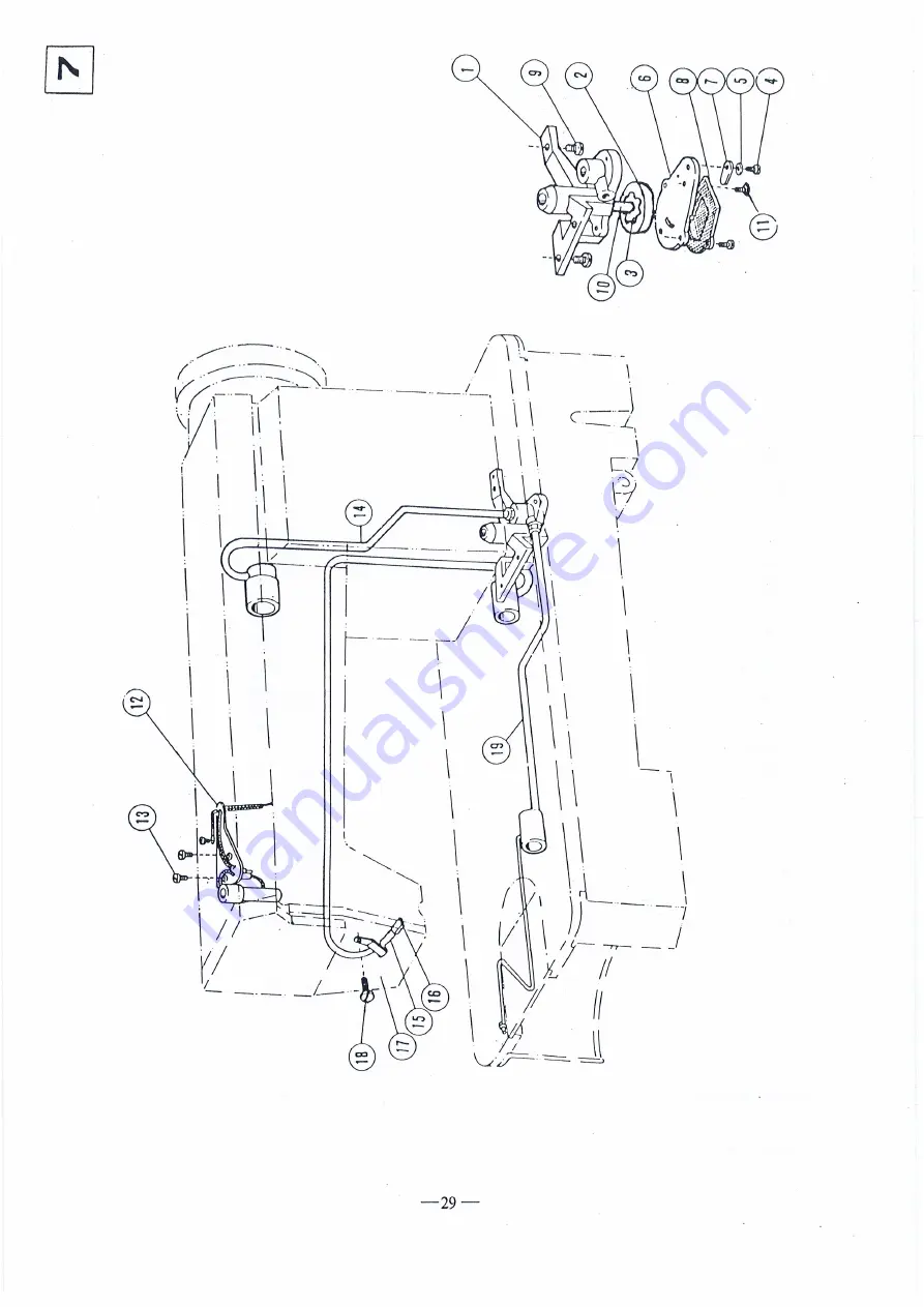
Page 34: ... 29 From the library of Superior Sewing Machine Supply LLC www supsew com ...

Page 35: ...er complete 22T8 008A 1 9 Screw for oil pump 22T8 009 3 10 Shaft for oil pump 15WF4 005 1 11 Screw 2 12 Oil wick set plate complete 22T8 001 1 13 Screw 22T8 012 2 14 Oil pipe complete for upper shaft 22T8 013 1 15 Oil return pipe 22T8 014 1 16 Oil felt 22T8 015 1 17 Oil return pipe clamp 22T8 016 1 18 Screw 22T8 004 1 19 Oil pipe complete for lower shaft 22T8 0l lB 1 I 30 From the library of Super...

Page 36: ... D E c 31 3 1 C Ja From the library of Superior Sewing Machine Supply LLC www supsew com ...

Page 37: ...Bell bracket 22T9 003B6 1 18 Screw 22T9 003B7 1 19 Pat 22T9 003B8 l 20 Split stop ring l 21 Belt guard complete 1KT6 00I l 22 Screw 2 23 Screw 2 24 Thread winder complete Sl4420020 l 25 Spool stand complete c1x 2 1 26 Oil tank 22T9 017 1 27 Magnet 22T9 013 l 28 Oil pot 33TF 0ll I 29 CUSHION 22T9 009 2 30 CUSHION 22T9 0IO 2 31 _ _ Hinge 33Tl 004 2 32 Rubber coat 22T9 007F2 2 33 Parts bag 33TF 010 1...

Page 38: ...From the library of Superior Sewing Machine Supply LLC www supsew com ...

Reviews: