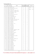
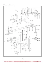
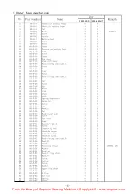
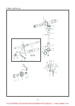
background image

3955-45DD

3955-45AUT

33
34

Side cover

From the library of Superior Sewing Machine & Supply LLC - www.supsew.com

Summary of Contents for WF3955-45AUT Series

Page 1: ...WF3955 45DD WF3955 45AUT Seris INSTRUCTION MANUAL BOOK PARTS BOOK GLOBALSEW COM DIRECT DRIVE TOP AND BOTTOM FEEN LOCKSTTICH SEWING MACHINE WITH AUTOMATIC THREAD TRIMMER ...

Page 2: ...ng the upper thread guide 10 21 Adjusting the presser foot height 10 22 Adjusting the feed dog height 10 23 Adjusting the feed dog angle 11 24 Adjusting the difference of stitch length between the forward and backtacking 11 25 Adjusting the tension release 11 26 Adjusting the timing of needle and feed mechanism 12 27 Adjusting the rotary hook lubrication amount 12 28 Adjusting the height of needle...

Page 3: ...Operation Instruction From the library of Superior Sewing Machine Supply LLC www supsew com ...

Page 4: ... m Max stitch length mm Needle bar stroo 37mm Ufting amount 3 5 5 Smm of presser feet Needle DPx17 23 IDPx17 25 Presser footlBvha d 8mm lifting height IBy H1ee 16mm Hook Large lubrication hook Lubrication Automatic lubrication Motor power 750W 3 Installing the oil pan Fig 1 1 Insert the two head cushion into the front corners of the oil pan CD 2 Insert the two head cushion into the back corners of...

Page 5: ...ine head onto the head cushions which are on the top of the oil pan comers 4 Tap the rest bar into the table hole NOTE Tap the rest bar securely into the table hole if not the machine head will not be safe when it is tilted back 5 Installing the knee lifter assy Fig 3 Insert the knee lifter assy D into the shaft under the oil pan and slightly tight the screw From the library of Superior Sewing Mac...

Page 6: ... the knee lifter plate is fully pressed 8 After adjustment tighten the nut 7 Lubrication Fig 5 1 0il amount Please fill the oil according to the mark indicated on the oil pan Mark A means the highest position Mark B means the lowest position if the oil amount is lower than the Mark B oil will not be pumped and machine will be jammed 2 Fill the oil Please fill the 18 sewing oil into the oil pan unt...

Page 7: ...he arm and face plate fully lubricate the parts showed by the arrows Install the face plate again lift the presser foot and operate the machine at a lower speed of 1000 lS00spm and observe the oil running through the oil gauge window After one month then the speed can be increased according to the different sewing operation From the library of Superior Sewing Machine Supply LLC www supsew com ...

Page 8: ...aw the bobbin case out of the hook 11 Winding the bobbin thread Fig 9 1 Turn the power on 2 Place the bobbin CD onto the bobbin winder shaft 3 Wind the thread several circles around the bobbin in the direction indicated by arrow 4 Push down the bobbin presser arm 5 Life the presser foot 6 Depress the treadle the winding operation will start 7 0nce finished the bobbin presser arm will release autom...

Page 9: ...f the notch 4 Check that the bobbin should tum clockwise if the thread is pulled 5 Hold the latch and p Iace the bobbin case in the hook I1a Threading the needle thread Fig 11 I Raise the thread take up lever to its highest posistion This will make threading easier and will prevent the thread from coming out at the sewing start Threading as below if the resistance of thread is large hreadtrai ls 1...

Page 10: ... will be when turn the dial from a larger setting to a smaller setting it will be easy to turn if the reverse lever is pressed down I15 Sewing and backtacking Fig 13 1 Turn the power on 2 Depress the treadle to start sewing When the reverse lever CD is pressed or the backtacking button is on during sewing the feed will be reversed After release the feed will recover to normal 7 0 From the library ...

Page 11: ...hread tension adjust the needle thread tension so that a good even stitch seam is obtained 1 Lower the presser foot 2 Adjust by turing the thread tension nut 8 7 Adjusting the presser foot pressure Fig 1 5 I Adjusting the presser foot pressure 1 Loosen the lock nut CD 2 Turn the adjusting screw to adjust the pressure of presser foot if it s not enough please tum the screw to increase the pressure ...

Page 12: ...resser foot 2 Loosen the screw 3 Turn the thread tension bracket to adjust the spring position 4 Tighten the screw The standard tension of the spring is 0 3 0 6N 5 Push the needle thread with your finger until it is slightly higher than the thread tension bracket and so that the upper thread is not pulled out 6 Pull the needle thread down until the spring CD is at the same height with the upper su...

Page 13: ...read take up tension 21 Adjusting the presser foot height Fig 19 The standard height of predder foot CD is 8mm when it is lifted by hand 1 Loosen the screw to lift the presser bar 2 Put a measurement gauge with 8mm height under the presser foot 3 Loosen the screw and adjust the height of presser foot 4 Tighten the screw I 22 Adjusting the feed dog height Fig 20 I 1 Set the stitch length maximum wh...

Page 14: ...ference of stitch length between the forward snd backtacking Fig 22 1 Remove the rear cover 2 Loosen the screw CD and turn the connecting stud Turn the stud clockwise the forward stitch length will be longer and the backtacking stitch length will be shorter Turn the stud counterclockwise the forward stitch length will be shorter and the backtacking stitch length will be longer 3 Tighten the screw ...

Page 15: ...heel UD slightly lower than the reference mark screw 3 Continue to turn the machine pulley set the second screw of eccentric wheel UD as refernce mark make the third screw CT of feed cam slightly higher than the reference mark screw 4 If need a non timing position loosen the three screw of eccentric wheel UD adjust the eccentric cam in the direction of arrow A or B To increase the tension of threa...

Page 16: ...enter of needle 1 Turn the machine pulley to raise the needle bar CD from its lowest position until the reference line B is aligned with the bottom edge of the needle bar bush When the needle bar moves up 2mm the clearance between the upper pf needle hole and the hook tip should be 1 3 1 8mm 2 Loosen the screw J and make the hook tip aimed at the center of needle the clearance between the hook tip...

Page 17: ...he materials to be sewm Loosen the screw and move the screw upward to increase the lifting amount of move the screw downward to decrease the lifting amount 3 Adjusting the forward backward clearance of the two feet To keep the front groove of walking foot not strike the rear of the presser foot the clearance of C must be kept about 3mm Loosen the screw of feed arm R and then turn the feed rock sha...

Page 18: ...The clearance between fixed knife CD and movable knife shoule be 0 3mm 2 Adjust the position illustrated by the Fig 30 3 Move the bobbin case opener and adjust the holder of fixed knife 3 Thread trimmer cam lever shaft Fig 31 l Install the shaft CD on the machine bed first 2 Install the cam lever Lon the shaft CD as illustrated 3 Slightly turn the shaft CD and install the positioning block as illu...

Page 19: ...en fix the cam 3 Set the solenoid inactive and make the cam lever restore to the original position there should be a 0 5 1 0mm clearance between cam and roller 6 Adjusting the knices Fig 34 l The relation between fixed knife and movable knife The clearance between movable knife CD and needle center is 7 Smm and the clearance betwwwn fixed knife and needle center is 5mm 2 Set the solenoid active th...

Page 20: ...plate 6 Turn the machine pulley and lift the needle above the needle plate check if the needle tip is blunt if yes change a new one 7 Tilt back the machine head 8 Remove the bobbin case 9 Clean the hook with a soft cloth and check if the hook is worn out 10 Take out the bobbin from the bobbin case and clean the bobbin case with a soft cloth 11 Insert the bobbin into the bobbin case and place the b...

Page 21: ...Parts Manual From the library of Superior Sewing Machine Supply LLC www supsew com ...

Page 22: ... e 14 3 14 14 4 t 14 6 2 3 37 2 37 4 37 1 37 37 5 6 7 5 37 6 37 8 37 7 8 9 37 10 f 37 9 11 10 18 11 t 16 19 12 14 15 13 35 1 0 42 20 47 f 48 r O rr 42 1 42 2 42 3 42 5 From the library of Superior Sewing Machine Supply LLC www supsew com ...

Page 23: ...ut 1 1 14 2 G09 1 14 2 Tension spring 1 1 14 3 G09 1 14 3 Thread tension disk presser 2 2 14 4 G09 1 14 4 Thread tension guide 1 1 14 5 G09 1 14 5 Tension post 1 1 14 6 G09 1 14 6 Tension nut 1 1 15 G09 1 15 Motor asm 1 550W G09 1 15 Motor asm 1 750W 16 G09 1 15 Washer 4 4 17 G09 1 15 Spring washer 4 4 18 G09 1 15 Screw 4 4 19 G09 1 15 Hand wheel 1 1 20 G09 1 15 Screw 2 2 21 Gl0 1 21 Magnets 1 22 ...

Page 24: ...4 2 e 14 3 14 14 4 t 14 6 2 3 37 2 37 4 37 1 37 37 5 6 7 5 37 6 37 8 37 7 37 10 f 37 9 11 10 20 11 t 16 19 12 14 15 13 35 1 0 42 20 47 f 48 r rr 42 1 42 2 42 3 42 5 From the library of Superior Sewing Machine Supply LLC www supsew com ...

Page 25: ...ion 2 2 37 7 G09 l 37 7 Disc presser 1 1 37 8 G09 l 37 8 Tension spring 1 1 37 9 G09 l 37 9 Stopper 1 1 37 10 G09 1 37 10 Tension nut 1 1 38 G09 1 38 Set screw 1 1 39 G09 1 39 Magnet cord rubber 1 1 40 G09 1 40 Thrad guide 1 1 41 G09 1 41 Screw 1 1 42 G09 1 42 Screw 1 1 42 1 G09 1 42 1 Tension disc 1 1 42 2 G09 1 42 2 Thrad guide 1 1 42 3 G09 1 42 3 Pre tension stud 2 2 42 4 G09 1 42 4 Tension spr...

Page 26: ...2 N e e d l eb a ra n dt h r e a dt a k e u pm e c h a n i s m 47 46 14 32 34 27 22 From the library of Superior Sewing Machine Supply LLC www supsew com ...

Page 27: ...24 Needle bar 1 1 25 G09 2 25 Thread guide 1 1 26 G09 2 26 Needle 1 1 DP 17 23 27 G09 2 27 Set screw 1 1 28 G09 2 28 Guide 1 29 G09 2 29 Slide block 1 1 30 G09 2 30 Screw 2 31 G09 2 31 Needle bar clamp assy 1 1 31 1 G09 2 31 1 Needle bar clamp 1 1 31 2 G09 2 31 2 Set screw 1 1 32 Gl0 2 32 Screw 1 33 Gl0 2 33 Wire holder U 1 34 Gl0 2 34 Wire holder D 1 35 G09 2 35 Washer 1 1 37 Gl0 2 37 Screw 2 38 ...

Page 28: ...3 Presser foot mechanism 15 8 11 21 i 22 El 9 J 13 r 12 14 20 2 10 1 f b 4 3 17 24 From the library of Superior Sewing Machine Supply LLC www supsew com ...

Page 29: ...12 G09 3 12 Spring extension 1 1 13 G09 3 13 Knee lifter bar 1 1 14 G09 3 14 Spring hook 1 1 15 G09 3 15 Shoulder screw 1 1 16 G09 3 16 Bush 1 1 17 G09 3 17 Presser bar 1 1 18 G09 3 18 Guide bracket 1 1 19 G09 3 19 Screw 2 2 20 G09 3 20 Spring compression 1 1 21 G09 3 21 Adjusting screw presser 1 1 22 G09 3 22 Adjusting nut presser 1 1 23 G09 3 23 Presser foot inside 1 1 24 G09 3 24 Screw 1 1 25 G...

Page 30: ...4 Feed mecha n1sm 40 o 21 30 31 33 12 7 _ 10 21 2 26 48 13 71 From the library of Superior Sewing Machine Supply LLC www supsew com ...

Page 31: ...m 1 1 19 G09 4 19 Pin 1 1 20 G09 4 20 Bush L 1 1 21 G09 4 21 Washer 2 2 22 G09 4 22 Feed lifting arm 1 1 23 G13 4 23 Shaft 1 1 24 G09 4 24 Screw 1 1 25 G09 4 25 Screw 1 1 26 G09 4 26 Connecting stud 1 1 27 G09 4 27 Feed regulator 1 1 28 G09 4 28 Screw L 1 1 29 G09 4 29 Screw S 1 1 30 G09 4 30 Bush 1 1 31 G09 4 31 Shaft 1 1 32 G09 4 32 Rubber cap 1 1 15 7 33 G09 4 33 Pin assy lever 1 1 34 G09 4 34 ...

Page 32: ...4 Feed mechanism 28 ___ I I f 0 63 t 58 57415 0 6 17 77 19 23 12 18 From the library of Superior Sewing Machine Supply LLC www supsew com ...

Page 33: ... 53 Link 2 2 54 G09 4 54 Set screw 1 1 55 G09 4 55 Link 2 2 56 G09 4 56 Shaft 1 1 57 G09 4 57 Screw 1 1 58 G09 4 58 Screw 1 1 59 G09 4 59 Shaft 1 1 60 G09 4 60 Feed regulator crank 1 1 61 G09 4 61 Pin shaft L 1 1 62 G09 4 62 Screw 1 1 63 G09 4 63 Pin shaft R 1 1 64 G09 4 64 Stopper 1 1 65 G09 4 65 Spring 1 1 66 G09 4 66 Eccentric wheel 1 1 67 G09 4 67 Screw 3 3 68 G09 4 68 Holder 1 1 69 G09 4 69 F...

Page 34: ...d mechanism 5 Upper fee 21 59 26 32 60 16 1s EJ 12 30 45 48 61 31 5 1 2 From the library of Superior Sewing Machine Supply LLC www supsew com ...

Page 35: ...29 Crank 1 2 30 G09 5 30 Stud 1 1 31 G09 5 31 Spring compression 1 1 32 G09 5 32 Guide bar 1 1 33 G09 5 33 Screw 1 34 G09 5 34 Nut 1 1 35 G09 5 35 Bush L 1 1 36 G09 5 36 Nut 1 1 37 G09 5 37 Feed rocker arm 1 1 38 G09 5 38 Screw 1 1 39 G09 5 39 Set screw 1 1 40 G09 5 40 Stud 1 1 41 G09 5 41 Eccentric wheel 1 1 42 G09 5 42 Screw 2 2 43 G09 5 43 Connecting rod 1 1 44 G09 5 44 Shoulder screw 1 1 45 G0...

Page 36: ...6 Hook mechanism 3 5 18 17 32 22 21 12 15 14 10 11 32 From the library of Superior Sewing Machine Supply LLC www supsew com ...

Page 37: ...4 G09 6 15 G09 6 16 Lower shaft Lower shaft Filter Screw Bush lower shaft L Gl0 6 16 Bush lower shaft L G09 6 17 G09 6 18 G09 6 19 G09 6 20 G09 6 21 G09 6 22 G09 6 23 G09 6 24 G09 6 25 G09 6 26 G09 6 27 Adjusting screw oil Adjusting screw Collar Screw Bush lower shaft R Screw Plunger Spring Hold plat Screw B case holder position bracket G09 6 28 Screw G09 6 29 Bush lower shaft M G09 6 30 Holder pl...

Page 38: ...33 34 7 Lubrication mechanism 34 From the library of Superior Sewing Machine Supply LLC www supsew com ...

Page 39: ...e assy 1 1 15 G09 7 15 Holder 1 1 16 G09 7 16 Screw 1 1 17 G13 7 17 Oil tube L 1 1 18 G09 7 18 Oil wick 1 1 I 19 19 G09 7 19 Rubber cap 4 4 1 11 8 20 G09 7 20 Rubber cap 2 2 1 8 8 21 G09 7 21 Rubber cap 1 1 I 27 22 G09 7 22 Rubber cap 1 1 I 5 7 23 G09 7 23 Rubber cap 1 1 24 G09 7 24 Oil gauge window 1 1 25 G09 7 25 Back cover 1 1 26 G09 7 26 Rubber cap 1 1 I 25 5 27 G09 7 27 Packing 1 1 28 Gl3 7 2...

Page 40: ... 3955 45AUT mechanism d trimming 8 Threa 2 I 3 4 T 5 29 30 64 l 47 48 8 66 42 36 From the library of Superior Sewing Machine Supply LLC www supsew com ...

Page 41: ...Gl0 8 15 Wire holder 1 16 Gl0 8 16 Terminal pin 2 17 Gl0 8 17 Pin 1 18 Gl0 8 18 Retaining ring 2 19 G14 8 19 Tension release wire 1 20 Gl0 8 20 Nut 2 21 Gl0 8 21 Tension release lever 1 22 Gl0 8 22 Screw 1 23 Gl0 8 23 Nut 1 24 Gl0 8 24 Holder F knife 1 25 Gl0 8 25 Lower thread finger 1 26 Gl0 8 26 Screw 1 27 Gl0 8 27 Screw 1 28 Gl0 8 28 Fixed knife 1 29 Gl0 8 29 Holder M knife 1 30 Gl0 8 30 Nut 2 ...

Page 42: ... 45AUT mechanism d tr imm1 ng 8 Threa 2 I 3 ii ai 4 T 5 1 t 11 62 J 29 39 38 37 36 0 34 35 t1 34 33 v 30 64 42 38 60 l 44 8 a6 13 i 65 64 From the library of Superior Sewing Machine Supply LLC www supsew com ...

Page 43: ... block 1 47 Gl0 8 47 Spring 1 48 Gl0 8 48 Screw 2 49 Gl0 8 49 Collar 1 50 Gl0 8 50 Plastic ring 1 51 Gl0 8 51 Thread trimmer cam lever L 1 52 Gl0 8 52 Screw 2 53 Gl0 8 53 Roller 2 54 Gl0 8 54 Nut 2 55 Gl0 8 55 Thread trimmer solenoid base 1 56 Gl0 8 56 Seal washer big 1 57 Gl0 8 57 Screw 3 58 Gl0 8 58 Washer 1 59 Gl0 8 59 Seal washer small 1 60 Gl0 8 60 Connector 1 61 Gl0 8 61 Cover 1 62 Gl0 8 62 ...

Page 44: ... 3955 45AUT 9 Revere stitching mechanism 12 13 22 21 21 5 L 20 40 From the library of Superior Sewing Machine Supply LLC www supsew com ...

Page 45: ...racket 1 10 6 Gl0 9 10 6 Spring 1 10 7 Gl0 9 10 7 Actuator 1 10 8 Gl0 9 10 8 Baffle 1 10 9 Gl0 9 10 9 Screw 2 11 Gl0 9 11 Solenoid cover 1 12 Gl0 9 12 Screw 1 13 Gl0 9 13 Washer 1 14 Gl0 9 14 Space collar 1 15 Gl0 9 15 Pin 1 16 Gl0 9 16 Connecting lever 1 17 Gl0 9 17 Solenoid lever 1 18 Gl0 9 18 Pin 1 19 Gl0 9 19 Screw 1 20 Gl0 9 20 Cord holder 1 21 Gl0 9 21 Clip wire Electromagnet asm 1 21 1 Gl0 ...

Page 46: ...32 1O Accessories for model 19 21 14 5 2 J 42 From the library of Superior Sewing Machine Supply LLC www supsew com ...

Page 47: ... 1 1 14 G09 10 14 Oil pot 1 1 15 G09 10 15 Head hinge 2 2 16 G09 10 16 Cushion head hinge 2 2 17 G09 10 17 Head cushion L 2 2 18 G09 10 18 Head cushion S 2 2 19 G09 10 19 Oil tank 1 1 20 G09 10 20 Thread stand assy 1 1 21 G09 10 21 Head rest 1 1 22 G09 10 22 Wrench 1 1 23 G09 10 23 Wrench 2mm 1 1 2GB T5356 1998 24 G09 10 24 Wrench 3mm 1 1 3GB T5356 1998 25 G09 10 25 Wrench 2 5mm 1 1 2 58GB T5356 1...

Page 48: ... 14 G10 11 15 G10 11 16 G10 11 17 1 1 1 4 4 4 1 2 1 2 1 4 1 3 1 1 1 Electromagnet ASM Side plate Gasket Washer NUT M5 Screw M5 L 12 Connection pin E RING 4 Electromagnet crank Thrust collar Screw M5 L 8 Screw 11 64 40 L 5 Bushing Screw M4 L 10 Nut of bushing M16 1 5 Transmission shaft Electromagnet shield 1 5 18 G10 11 18 2 Screw M4 L 5 11 Presser foot lifting set mechanism Option parts 11 Presser...

Page 49: ...9 12 l Control asm Gl0 12 1 Control asm 2 G09 12 2 Power switch 3 G09 12 3 Control cover Gl0 12 3 Control cover 4 G09 12 4 Control panel asm Gl0 12 4 Control panel asm 5 G09 12 5 Power line 6 G09 12 6 Screw M 5 7 G09 12 7 Screw M 5 8 G09 12 8 Screw M 5 9 G09 12 9 Treadle asm 10 G09 12 10 Li ve fes t i val ball 1i nk asm L Qty RP mark 1 1 1 1 1 1 1 1 1 1 1 1 1 1 1 1 1 1 1 1 ...

Page 50: ...5 G13 13 06 G13 13 07 G13 13 08 G13 13 09 G13 13 10 G13 13 11 G13 13 12 G13 13 13 G13 13 14 2 1 4 2 4 1 2 1 2 1 1 1 1 1 Knee shaft bracket Lifter shaft Screw Feed lifting crank Screw M5 Collecting rod Shoulder screw Bracket Screw M8 Cover K lifter plate Knee lifter plate Lifter bar Stopper Screw M6 46 3955 45DD 3955 45AUT 2 1 4 2 4 1 2 1 2 1 1 1 1 1 13 Accessories for model WF3955 45DD WF3955 45AU...

Page 51: ...OLOBAL GLOBALSEW COM ...

Reviews: