INSTRUCTION MANUAL
Issue.
08 / 2004
Pag.
13 - 42
WARNING
DANGER
6.2.3
EMERGENCY
In case of temporary lack of power, the down stroke and the inclination movement may be
stopped.
This situation can be solved by operating manually on the opening of the down stroke valves both
of the:
-
lifting cylinder
and the
-
inclination cylinder
The
emergency down stroke valves
are placed inside the operating unit (front side) of the
cabinet.
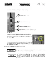
They are positioned on the engine/hydraulic pump unit (see detail, Picture
B
).
In order to reach them you need to unscrew the nuts on the electro-valves’s coils.
After removing the nuts, you will see two small round knurled knobs which must be unscrewed
very slowly (anticlockwise rotation) in order to obtain:
-
Left knob.
(mark
B1
) Inclination Cylinder down stroke.
Therefore if the bench was stopped at an inclined position, with this operation the bench will
be positioned again horizontally.
-
Right know.
(mark
A1
) Lifting Cylinder down stroke.
Therefore if the bench was stopped at a certain height with this operation the bench will be
positioned again at its minimum height.
The knobs must be always unscrewed very slowly e and the down
stroke speed should be kept moderate. At the end of any operation you
should screw tight the knobs and reposition the nuts on their original
position..
If there is no power all the safety and control systems are excluded.
All operations carried out on the lift are therefore under the operator’s
control and responsibility.
Summary of Contents for Super Rotax
Page 2: ...USERS MANUAL Year of Manufacture ...
Page 21: ...INSTRUCTION MANUAL Issue 08 2004 Pag 19 42 7 1 1 ELECTRICAL PLANT DIAGRAM ...
Page 22: ...INSTRUCTION MANUAL Issue 08 2004 Pag 20 42 7 1 2 HYDRAULIC PLANT DIAGRAM ...
Page 23: ...INSTRUCTION MANUAL Issue 08 2004 Pag 21 42 7 1 3 PNEUMATIC PLANT DIAGRAM ...
Page 42: ...INSTRUCTION MANUAL Issue 08 2004 Pag 40 42 14 OVERALL DIMENSIONS DRAWING ...


