INSTRUCTION MANUAL
Issue.
08 / 2004
Pag.
14 - 42
6.3
PNEUMATIC CONNECTION (to the lifting bench)
Connect the blue pipe of air feed for mechanical safety,
inserting and pushing it to the bottom of the bracket, as shown
in
Picture 6-07
Î
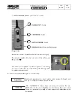
The connection point to the network is placed è situato (a
mezzo raccordo rapido passa-parete) bottom left of the back
side of the cabinet. The plate shows the feeding entry and the
values of the pressure, see
Picture 6-08
Î
Use pipe Ø 8. (pipe RILSAN Ø 6x8)
The feeding data and the characteristics of compressed air are
listed in the table here below.
DESCRIPTION VALUE
Compressed air type
dry
Air filtering max/min
5 ~ 15
μ
Air lubrication
yes
Oil type
See Oil Table
Humidity outlet disposal
yes
Air pressure
6 ÷ 8 bar
Table of Oils for Air Lubrication (ISO 3448)
CLASSE
ISO VG 32
ISO VG 32
ISO VG 10
ELF
Spinelf 22
Olna 22
TOTAL
Azolla 32
ZS 32
SHELL
Tellus S 22
Tellus
C10
ESSO Spinesso
22
Spinesso
10
MOBIL DTE
light
DTE
21
BP
HPL 22
HPL 32
Energol HPE 10
WARNING
Any lack of pressure or air, or any other problem to the mechanical safety
system avoids the down stroke but not the up stroke of the lift.
Summary of Contents for Super Rotax
Page 2: ...USERS MANUAL Year of Manufacture ...
Page 21: ...INSTRUCTION MANUAL Issue 08 2004 Pag 19 42 7 1 1 ELECTRICAL PLANT DIAGRAM ...
Page 22: ...INSTRUCTION MANUAL Issue 08 2004 Pag 20 42 7 1 2 HYDRAULIC PLANT DIAGRAM ...
Page 23: ...INSTRUCTION MANUAL Issue 08 2004 Pag 21 42 7 1 3 PNEUMATIC PLANT DIAGRAM ...
Page 42: ...INSTRUCTION MANUAL Issue 08 2004 Pag 40 42 14 OVERALL DIMENSIONS DRAWING ...


