


INSTRUCTION MANUAL
Issue.
08 / 2004
Pag.
15 - 42
WARNING
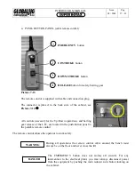
6.4
CONNECTION TO THE ELECTRIC NETWORK
6.4.1
TO THE LIFTING BENCH, LOW TENSION 24V
-
Insert the plug of the up stroke-end cable, making yourself sure of the correct connection, as
shown in the pictures here below
Ó
Picture 6-09
and
Picture 6-10
Ô
if the connection is not correct o or any other problem to this link will
totally inhibit the equipment operating.
-
At the end of the above operations and before supplying power to the plant, you should protect
all the elements of the plant with the supplied profiles fixed to the floor. (see
Picture 6-11
)
This operation is NECESSARY only if it is not possible to lay the cable underground.
Photo 6-11
Profile / L. 2000 each
Summary of Contents for Super Rotax
Page 2: ...USERS MANUAL Year of Manufacture ...
Page 21: ...INSTRUCTION MANUAL Issue 08 2004 Pag 19 42 7 1 1 ELECTRICAL PLANT DIAGRAM ...
Page 22: ...INSTRUCTION MANUAL Issue 08 2004 Pag 20 42 7 1 2 HYDRAULIC PLANT DIAGRAM ...
Page 23: ...INSTRUCTION MANUAL Issue 08 2004 Pag 21 42 7 1 3 PNEUMATIC PLANT DIAGRAM ...
Page 42: ...INSTRUCTION MANUAL Issue 08 2004 Pag 40 42 14 OVERALL DIMENSIONS DRAWING ...


