


Issue.
08 / 2004
Pag.
25 - 42
INSTRUCTION MANUAL
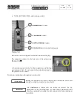
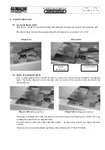
General switch with lock
2.
Tension warning light
3.
Warning plate
4.
Technical data plate
5.
Bench inclination button
6.
Cover locking
7.1.5
CONTROLS DESTINATION AND INTERVENTION
1.
GENERAL SWITCH
This control must be activated when you begin to
sabled at the end of
its use. L'interruttore è del tipo rotativo blocca porta lucchettabile.
Position
CONTROL CONSOLE
Picture 7-08
3
4
5S+5D
1.
work with the lift and di
O
(open)
All circuits are with no tension
Position
I
(closed)
All circuits are under tension
2.
TENSION WARNING LIGHT
It signals the presence of electic tension in the circuits and the position of the general
switch
À
.
I
1
6
2
Summary of Contents for Super Rotax
Page 2: ...USERS MANUAL Year of Manufacture ...
Page 21: ...INSTRUCTION MANUAL Issue 08 2004 Pag 19 42 7 1 1 ELECTRICAL PLANT DIAGRAM ...
Page 22: ...INSTRUCTION MANUAL Issue 08 2004 Pag 20 42 7 1 2 HYDRAULIC PLANT DIAGRAM ...
Page 23: ...INSTRUCTION MANUAL Issue 08 2004 Pag 21 42 7 1 3 PNEUMATIC PLANT DIAGRAM ...
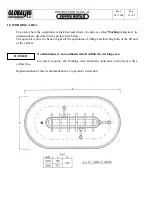
Page 42: ...INSTRUCTION MANUAL Issue 08 2004 Pag 40 42 14 OVERALL DIMENSIONS DRAWING ...


