


INSTRUCTION MANUAL
Issue.
08 / 2004
Pag.
26 - 42
WARNING
ATTENZIONE
Therefore the operator must be sure th
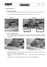
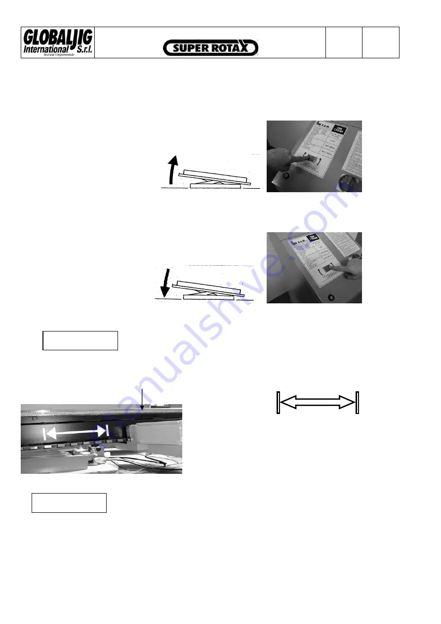
3.
BENCH INCLINATION
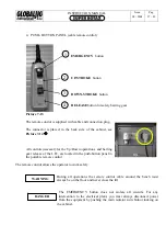
The two buttons
5S
e
5D
control the bench inclination.
-
By pushing the button
5S
the bench makes a
frontward inclination.
Picture 7-09
-
By pushing the button
5D
the bench returns to its
original position.
Picture
7-10
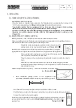
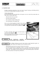
The inclination of the bench is intended and permitted only for loading and
removing the vehicle. When the bench is inclined it is absolutely forbidden to
move the pulling towers.
Before carrying out the above operations please read the following instructions:
Picture 7-11
Picture 7-12
This white symbol, which is marked on both sides of the
bench, defines the Risk Zone for pulling arm damage. If
this latter, should be positioned within the Risk Zone
during the inclination stage, damage may occur.
at during the inclination stage, the
pulling arm MUST BE KEPT OUT OF THE RISK ZONE.
The manufacturer is not responsible for any damage to the Lifting Bench caused if ignoring this
WARNING.
Summary of Contents for Super Rotax
Page 2: ...USERS MANUAL Year of Manufacture ...
Page 21: ...INSTRUCTION MANUAL Issue 08 2004 Pag 19 42 7 1 1 ELECTRICAL PLANT DIAGRAM ...
Page 22: ...INSTRUCTION MANUAL Issue 08 2004 Pag 20 42 7 1 2 HYDRAULIC PLANT DIAGRAM ...
Page 23: ...INSTRUCTION MANUAL Issue 08 2004 Pag 21 42 7 1 3 PNEUMATIC PLANT DIAGRAM ...
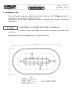
Page 42: ...INSTRUCTION MANUAL Issue 08 2004 Pag 40 42 14 OVERALL DIMENSIONS DRAWING ...


