INSTRUCTION MANUAL
Issue.
08 / 2004
Pag.
27 - 42
WARNING
DANGER
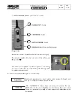
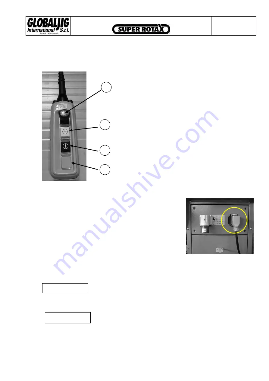
4. PUSH- BUTTON PANEL (cable remote control)
Picture 7-13
The remote control is supplied with cable and connection plug.
The connector is placed in the back side of the cabinet, see
Picture 7-14
Î
r the Up/Down operations and barring
cated in the push-button panel in
the portable remote control
The remo
ely .
During all operations the remote control cable around the bench must
always be on the floor and never cross the lift.
The EMERGENCY button does not isolate all circuits. For any
intervention to the electrical plant, you must always disconnect power
the equipment by pushing the main isolator switch/door locking on
1
EMERGENCY
button
2
UP-STROKE
button
3
DOWN-STROKE
button
4
RELEASE
button for safety barring gear
All controls necessary fo
gear release of the L.B:, are lo
te control allows the operator to work saf
from
the cabinet.
Summary of Contents for Super Rotax
Page 2: ...USERS MANUAL Year of Manufacture ...
Page 21: ...INSTRUCTION MANUAL Issue 08 2004 Pag 19 42 7 1 1 ELECTRICAL PLANT DIAGRAM ...
Page 22: ...INSTRUCTION MANUAL Issue 08 2004 Pag 20 42 7 1 2 HYDRAULIC PLANT DIAGRAM ...
Page 23: ...INSTRUCTION MANUAL Issue 08 2004 Pag 21 42 7 1 3 PNEUMATIC PLANT DIAGRAM ...
Page 42: ...INSTRUCTION MANUAL Issue 08 2004 Pag 40 42 14 OVERALL DIMENSIONS DRAWING ...


