INSTRUCTION MANUAL
Issue.
08 / 2004
Pag.
29 - 42
WARNING
7.2
ELECTRICAL SETUP CHECKS.
The operations for the first start are very important in order to assure a correct and lasting
functioning of the L.B.
Therefore, we recommend you to carry out the operations described below with the utmost care.
Check that the network voltage is the same as the one reported on the plate.
Check that the current is supplied with protection disposal (not included in the L.B. )
Check the good condition of the feeder and the presence of the earthed neutral
(yellow/green). Connect and place the earthed neutral with the utmost care
and according to the current regulations.
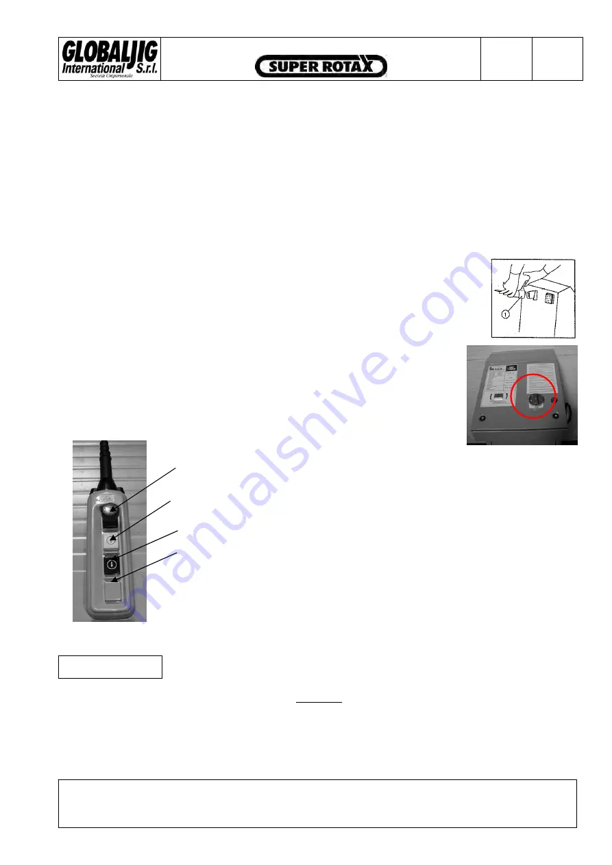
Insert the plug
À
in the outlet placed on the power unit console, see
Picture 7-
15
Î
Supply voltage to the L.B. by operating on the
main switch
sulla on the
console of the power unit, see
Picture 7-16
Î
Photo 7-17
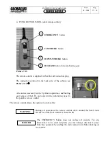
Use the remote control .
Check that the
button
À
for
EMERGENCY is
disabled. Now,
press button
Á
UP
only for few
seconds and check
that the lift is
moving.
If the lift does not move, do not insist because the wrong wiring rotation of the
engine, and therefore also of the hydraulic pump, may cause damage to the
hydraulic plant.
In this case invert the two phases of the feeder. DO NOT
À
EMERGENCY
Á
UP
Â
DOWN
Ã
SAFETY RELEASE
make any intervention on the terminal board of
the electric engine.
Test its correct functioning by carrying out a complete up and down stroke.
Make a final check "at sight" at all the pipes connections, at the junctions and at the cylinder in order to
find out eventual leaks of oil. In this case lock tight the junction in the leaks locations.
Not observing the above mentioned instructions cause the invalidation of the warranty conditions,
and any damage that may follow will not be imputed to the Manufacturer.
Summary of Contents for Super Rotax
Page 2: ...USERS MANUAL Year of Manufacture ...
Page 21: ...INSTRUCTION MANUAL Issue 08 2004 Pag 19 42 7 1 1 ELECTRICAL PLANT DIAGRAM ...
Page 22: ...INSTRUCTION MANUAL Issue 08 2004 Pag 20 42 7 1 2 HYDRAULIC PLANT DIAGRAM ...
Page 23: ...INSTRUCTION MANUAL Issue 08 2004 Pag 21 42 7 1 3 PNEUMATIC PLANT DIAGRAM ...
Page 42: ...INSTRUCTION MANUAL Issue 08 2004 Pag 40 42 14 OVERALL DIMENSIONS DRAWING ...


