INSTRUCTION MANUAL
Issue.
08 / 2004
Pag.
31 - 42
8.
OPERATING
8.1. VEHICLES LIFTING AND LOWERING
WARNINGS AND CAUTIONS
Once the bench is installed and connected, the Manufacturer recommends the testing of the
“L.B.” before standard use, by
lifting
and
lowering
the bench without any load.
You should consider that no equipment is free from any risk or danger while working,
therefore the Operator must pay special attention to these warnings.
In order to avoid any risk when first starting working on the equipment, we recommed the
Operator to read this chapter carefully, while for the Equipment Safety we advise to read
Chapter 8.4.
8.2. BEGINNING OF VEHICLE LIFTING
Starting situation: “L.B” completely lowered and vehicle read to be lifted..
Move one pulling tower on the most convenient position correspondent to the pulling direction
with the winch cable. Fix it in this position inserting its bolt.
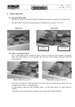
Mount the winch and support assembly on the vertical arm of the
pulling tower, at the most suitable height, see
Picture 8-01
Î
Push the first crossbeam to the front stop and lock it on both sides by using the
appropriate rack. Tighten the two bolts with the key supplied with the equipment.
Move out the other crossbeams in order to insert the ramps, one by
one on each two crossbeams on both sides.
Place the ramps on the crossbeams symmetrically in order to match the vehicle’
track.
Push the last crossbeam towards the rear end of the bench, dragging all other
crossbeams and the ramps until they are all compacted.. Lock the crossbem as you
did with the first one.
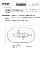
Mount and position the stop ramp
À
on the last crossbeam for vehicle safety.
See
Picture 8-02
Î
1.
Place additional pulling towers at the equipment edge
OUTSIDE THE RISK ZONE marked by the following symbol:
Now insert the two ramps and place them to match the vehicle’s track.
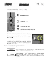
Push the button on the left of the power unit cabinet to activate the bench tilting mechanism.
Connect the winch to the power supply.
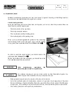
While one person unwinds the steel cable by pulling it with the winch hook, a second
person should push the winch control
bifunctional push -button
to the cable release
position. See
Picture 8-03
Î
Summary of Contents for Super Rotax
Page 2: ...USERS MANUAL Year of Manufacture ...
Page 21: ...INSTRUCTION MANUAL Issue 08 2004 Pag 19 42 7 1 1 ELECTRICAL PLANT DIAGRAM ...
Page 22: ...INSTRUCTION MANUAL Issue 08 2004 Pag 20 42 7 1 2 HYDRAULIC PLANT DIAGRAM ...
Page 23: ...INSTRUCTION MANUAL Issue 08 2004 Pag 21 42 7 1 3 PNEUMATIC PLANT DIAGRAM ...
Page 42: ...INSTRUCTION MANUAL Issue 08 2004 Pag 40 42 14 OVERALL DIMENSIONS DRAWING ...


