INSTRUCTION MANUAL
Issue.
08 / 2004
Pag.
33 - 42
ATTENTION
8.3.BEGINNING OF VEHICLE LOWERING
•
Starting situation: the vehicle is properly positioned on the ramps .
•
The crossbeams and the ramps are compacted as described in point 8.2.7.. The bench is positioned
at its working height "Standing man’s height".
•
Insert the stop ramps, both front and rear.
•
Lower the bench till the floor.
•
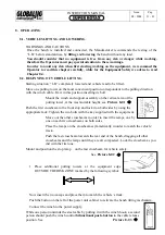
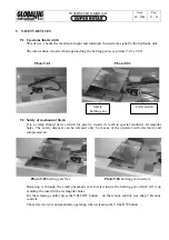
Place the pulling towers on the bench following the instructions and the warnings already
mentioned in the lifting operation. Mount the winch on the vertical arm.
•
Unwind the winch cable unitl you can hitch the vehicle.
•
Rewind the rest of the cable and hold the vehicle with the cable in tension.
•
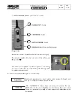
Push the button on the left of the power unit cabinet to tilt the bench frontward.
•
Remove the stop ramp on the front.
•
Insert the ramps and position them on the crossbeam to match the vehicle’s track.
•
Push the bifunctional push-button of the winch control to the cable release position.
•
Lower the vehicle until it leaves the bench.
•
Unfasten the winch hook.
This operation can be risky: for this reason it is advisable to watch the vehicle during its
descent and if necessary to intervene manually until the vehicles is on the floor.
END OF THE VEHICLE LOWERING OPERATION
Now the bench is ready and properly positioned to start a new repair job.
Summary of Contents for Super Rotax
Page 2: ...USERS MANUAL Year of Manufacture ...
Page 21: ...INSTRUCTION MANUAL Issue 08 2004 Pag 19 42 7 1 1 ELECTRICAL PLANT DIAGRAM ...
Page 22: ...INSTRUCTION MANUAL Issue 08 2004 Pag 20 42 7 1 2 HYDRAULIC PLANT DIAGRAM ...
Page 23: ...INSTRUCTION MANUAL Issue 08 2004 Pag 21 42 7 1 3 PNEUMATIC PLANT DIAGRAM ...
Page 42: ...INSTRUCTION MANUAL Issue 08 2004 Pag 40 42 14 OVERALL DIMENSIONS DRAWING ...


