background image


INSTRUCTION MANUAL 


Issue. 

08 / 2004 

Pag. 

37 - 42 


11.


START AND STOP – SAFETY PROCEDURES. 


11.1.


Start up operations 


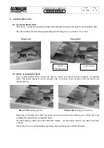
Starting position: the bench is completly lowered and it may be in one of the possible situations 
that follows. 

-


With crossbeams and bases 

-


With side runners 

-


With the Globaljig system and the vehicle already in position 

-


With side runners and vehicle 

 
Before activating the lifting bench: 

-


Check if the power is available. 

-


Check the Working Area, make sure that the area is free from objects or people.  

-


Check the correct position of the ramps. 

-


Check the load stability. 


11.2.


 Stopping operations 

 
At the end of the job or when you have to have a long break, you should: 


Reposition the bench horizontally and at its minimum height . 


Turn  off the main switch (on the power unit console) in position 

O.


11.3.


 Stopping operations in case of a blackout. 

 
In case of a blackout, the lifting bench is out of work and even if it is still safe, (the barring gear is 
activated), you must turn off the main switch on the console, until the power is restored. 


Summary of Contents for Super Rotax

Page 1: ...Via Aurelia Ovest Km 383 54100 Massa MS ITALY Tel 39 0585 8364 Fax 39 0585 833880 www globaljig it USERS MANUAL ...

Page 2: ...USERS MANUAL Year of Manufacture ...

Page 3: ...TICS AND TECHNICAL DATA 4 FREIGHT AND UNPACKING 5 INSTALLATION 6 COMMISSIONING 7 CONTROLS AND SET UP 8 OPERATING 9 SAFETY DEVICE 10 WORKING AREA 11 START STOP EMERGENCY 12 MAINTENANCE 13 REPAIR COMPONENTS AND SPARE PARTS 14 DIAGRAMS AND OVERALL DIMENSIONS 15 DEMOLITION APPEDIX CE CONFORMITY DECLARATION ...

Page 4: ... operating life of the equipment It must be consulted without causing damage It must be kept unabridged and complete as originally supplied If the ownership changes the Manual must accompany the Equipment The Manufacturer is not responsible in any way if the operator does not follow the instructions contained in this Manual if damage occurs or personal injury results from improper use of the Equip...

Page 5: ...ly indoors Installation must be carried out by Qualified Staff only and in accordance with the instructions given in this Manual Any modification of the equipment or tamperings with safety devices without permission of the manufacturer are considered as an infringement of the European Safety Standards We recommend the use of original components and spare parts only Any intervention to the electric...

Page 6: ...alla pulsantiera dell operatore ed in presenza dell energia elettrica e pneumatica Upstroke and downstroke are controlled by the operator by the remote control The crossbeams with base block which are parts of the Universal Jig GLOBALJIG are always on the bench and they have the double function of receiving the jigs or the side runners and ramps for positioning the vehicle for repair The tilt mech...

Page 7: ...HNICAL DATA Rated Votage 200 415 V 50 60 Hz Rated power 2 5 Kw Rated capacity 3500 kg Lifting Height 1750 mm Lifting lowering time 60 72 sec Oil pressure 200 bar L B mass values see drawing page 6 The Super Rotax equipment is produced in the following versions with 4 meters bench with 1 or 2 pulling arms with 5 meters bench with 1 or 2 pulling arms If not otherwise specified the technical data her...

Page 8: ...nside the packages All operations of loading and unloading packages must be carried out using specific procedures and methods as required by Health and Safety Regulations The assigned staff must wear the necessary protective clothing GLOBALJIG INTERNATIONAL srl desclaims all responsibility for damage to people and or objects caused when not observing the warnings the procedures and recommendations...

Page 9: ...e L B you should Consider the vehicle s side for lifting and lowering called Front Side The manufacturer plate pag 05 positioned on the first crossbeam of the bench deternines the Front Side please read chapter 10 Working Area and chapter 14 Overall Drawing After you have positioned the L B remove the wooden pallet from beneath the lift You can do this using standard jacks Fig 5 03 Proceeding with...

Page 10: ...l and has suitable bearing capability It is recommended that it should be able to bear a total weight of 9 000 daN with a specific pressure of 0 50 daN cm and made of the correct consistency necessary to allow a proper fixing of the anchoring plugs to the floor The plugs supplied with the equipment are 6 Ø 20x90 mm with M12 screws The plugs can be set and fixed only after electrical connection bec...

Page 11: ...N supplied from the network 6 1 POWER UNIT CABINET Once you have positioned the bench place the cabinet near its final position On the back side of the cabinet you will find See picture 6 01 e 6 02 Tuboflex A70066 lifting jack supply Tuboflex A70067 inclination jack supply Feed pipe blue A70072 for safety bolt release jack Cable and plug for up stroke end control Photo 6 01 Photo 6 A70072 A70066 A...

Page 12: ...two keys as shown in the picture untighten the caps placed on the bracket and on the cylinder connection Photo Ô untighten the caps at the end of the flexible feed pipes coming out of the cabinet Now connect the pipes to the connection on the bracket and the connection on the cylinder We advise to proceed quickly in order to avoid a leak of oil from the pipes Actually the plant is always supplied ...

Page 13: ...sue 08 2004 Pag 11 42 6 2 2 To the hydraulic power unit 6 2 2 1 see picture A Electric engine See detail picture B Pump unit Tank A EMERGENCY VALVES B Electro valves bench inclination up down Valves unit DETAIL VALVES UNIT ...

Page 14: ...l tank capacity lt 12 Advised oil type SHELL TELLUS or similar see table below SAE 32 Hydraulic oils Table Intervals of Temperature Up to 30 C From 30 C to 45 C Beyond 45 C Standard viscosity in Centistokes at 50 C 16 20 24 28 31 39 AGIP OSO 32 OSO 46 OSO 68 CASTROL HYSPIN AWS 32 HYSIN AWS 46 HYSPIN AWS 68 CHEVRON EP HYDR OIL 32 EP HYDR OIL 46 EP HYDR OIL 68 ESSO NUTO H 32 NUTO H 46 NUTO H 68 IP I...

Page 15: ...urled knobs which must be unscrewed very slowly anticlockwise rotation in order to obtain Left knob mark B1 Inclination Cylinder down stroke Therefore if the bench was stopped at an inclined position with this operation the bench will be positioned again horizontally Right know mark A1 Lifting Cylinder down stroke Therefore if the bench was stopped at a certain height with this operation the bench...

Page 16: ... pipe RILSAN Ø 6x8 The feeding data and the characteristics of compressed air are listed in the table here below DESCRIPTION VALUE Compressed air type dry Air filtering max min 5 15 μ Air lubrication yes Oil type See Oil Table Humidity outlet disposal yes Air pressure 6 8 bar Table of Oils for Air Lubrication ISO 3448 CLASSE ISO VG 32 ISO VG 32 ISO VG 10 ELF Spinelf 22 Olna 22 TOTAL Azolla 32 ZS 3...

Page 17: ...below Ó Picture 6 09 and Picture 6 10Ô if the connection is not correct o or any other problem to this link will totally inhibit the equipment operating At the end of the above operations and before supplying power to the plant you should protect all the elements of the plant with the supplied profiles fixed to the floor see Picture 6 11 This operation is NECESSARY only if it is not possible to la...

Page 18: ...ly is included as well For the connection use multipolar cable with a 4 conductors min Of 2 5 mm2 each 3 phases 1 ground yellow green according to the present regulations For the German market use pentapolar cable with same characteristics as above Standard functioning of the L B requires a three phase supply 400V and it is already provided for this voltage Before making any connection always chec...

Page 19: ...50 60Hz 415 V 60Hz Type of supply 3 phase T Ground connection compulsory Type of tension alternating Linea elettrica comandi segnali autonoma in B T 1 fase Standard tension value 200 415 V Special tension value a rich Tension value in B T 24 V Standard frequency value 50 Hz Special frequency value 60 Hz Installed rated power 2 5 kW ...

Page 20: ...draulic and pneumatic controls are located in the cabinet Together with the push buttons board remote control it includes all the controls necessary for the Lifting Bench operations All controls listed here below are described in the diagrams that follow Electrical Hydraulic Pneumatic ...

Page 21: ...INSTRUCTION MANUAL Issue 08 2004 Pag 19 42 7 1 1 ELECTRICAL PLANT DIAGRAM ...

Page 22: ...INSTRUCTION MANUAL Issue 08 2004 Pag 20 42 7 1 2 HYDRAULIC PLANT DIAGRAM ...

Page 23: ...INSTRUCTION MANUAL Issue 08 2004 Pag 21 42 7 1 3 PNEUMATIC PLANT DIAGRAM ...

Page 24: ...N MANUAL Issue 08 2004 Pag 22 42 7 1 4 CABINET DESCRIPTION Photo 7 02 Photo 7 01 Remote Control cable Front Side Identification plate for electric power Back side Connector for remote control Electric power plug ...

Page 25: ...2004 Pag 23 42 INSTRUCTION MANUAL Issue 08 SWITCHBOARD under the cover Photo 7 03 Photo 7 04 Photo 7 05 Line fuses Transformer fuses 1 2 1 1 2 Fuses Box n 3 fuses G10A n 2 fuses G2A 1 2 Cover ...

Page 26: ...INSTRUCTION MANUAL Issue 08 2004 Pag 24 42 HYDRAULIC POWER UNIT front door side Photo 7 06 Photo 7 07 Power unit valves location Pneumatic electro valve mechanical safety control ...

Page 27: ...This control must be activated when you begin to sabled at the end of its use L interruttore è del tipo rotativo blocca porta lucchettabile Position CONTROL CONSOLE Picture 7 08 3 4 5S 5D 1 work with the lift and di O open All circuits are with no tension Position I closed All circuits are under tension 2 TENSION WARNING LIGHT It signals the presence of electic tension in the circuits and the posi...

Page 28: ... and removing the vehicle When the bench is inclined it is absolutely forbidden to move the pulling towers Before carrying out the above operations please read the following instructions Picture 7 11 Picture 7 12 This white symbol which is marked on both sides of the bench defines the Risk Zone for pulling arm damage If this latter should be positioned within the Risk Zone during the inclination s...

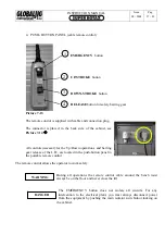
Page 29: ...rol The remo ely During all operations the remote control cable around the bench must always be on the floor and never cross the lift The EMERGENCY button does not isolate all circuits For any intervention to the electrical plant you must always disconnect power the equipment by pushing the main isolator switch door locking on 1 EMERGENCY button 2 UP STROKE button 3 DOWN STROKE button 4 RELEASE bu...

Page 30: ...ht the limit switch stops the plant immediately N B for the safety stopping press only button  The bench lowers till the inserting of the barring gear 3 DOWN STROKE If the L B is in safety stopping position press for a moment button Á for the up stroke then press and keep it pressed button à only afterwards press button  In this way the bench starts its down stroke and will keep till it reaches ...

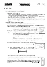
Page 31: ...la on the console of the power unit see Picture 7 16Î Photo 7 17 Use the remote control Check that the button À for EMERGENCY is disabled Now press button Á UP only for few seconds and check that the lift is moving If the lift does not move do not insist because the wrong wiring rotation of the engine and therefore also of the hydraulic pump may cause damage to the hydraulic plant In this case inv...

Page 32: ...ld stand in the lift working area the vehicle is steadily positioned During the UP DOWN operations it is advisable to watch the L B and its load At the end of the up down operations of the L B it is advisable to position the main switch on the console on the O In case of black out the L B il B S is out of work but the antifall security valve will be still operating ...

Page 33: ...t suitable height see Picture 8 01 Î Push the first crossbeam to the front stop and lock it on both sides by using the appropriate rack Tighten the two bolts with the key supplied with the equipment Move out the other crossbeams in order to insert the ramps one by one on each two crossbeams on both sides Place the ramps on the crossbeams symmetrically in order to match the vehicle track Push the l...

Page 34: ...s place insert the stop ramp Remove the second ramp from the crossbeam Push the button on the right of the unit power cabinet in oder to bring the bench to its horizontal position Unfasten the winch hook and rewind the remaining part of the cable Remove the winch This operation can be risky it is advisable to watch the vehicle while it goes on the bench following its track and if necessary to inte...

Page 35: ...able unitl you can hitch the vehicle Rewind the rest of the cable and hold the vehicle with the cable in tension Push the button on the left of the power unit cabinet to tilt the bench frontward Remove the stop ramp on the front Insert the ramps and position them on the crossbeam to match the vehicle s track Push the bifunctional push button of the winch control to the cable release position Lower...

Page 36: ...LE For the use of trained operators only It is forbidden to use this lift for any other purpose different from those provided in this instruction manual Do not allow anyone on or inside the loaded vehicle or on the structure of the lift It is forbidden to overload the lift exceeding its maximum capacity Be sure that the weight of the vehicle to be lifted and its distribution are in conformity with...

Page 37: ...serts its teeth in special moulded rectangular holes The safety disposal can be released only by means of the operator with electricity and compressed air Photo 9 03 barring gear free Photo 9 04 barring gear inserted Releasing is through the small pneumatic ram located inside the barring gear which lift it up avoiding the insert in the rectangular holes For the releasing control press the YELLOW b...

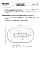
Page 38: ...re described in the picture here below The operator is able to check at sight all the operations of lifting and lowering both of the lift and of the vehicle No admittance to non authorized staff within the working area For safety reasons the Working Area should be indicated on the floor with a yellow line Implementation of this recommendation is at operator s discretion ...

Page 39: ...vailable Check the Working Area make sure that the area is free from objects or people Check the correct position of the ramps Check the load stability 11 2 Stopping operations At the end of the job or when you have to have a long break you should Reposition the bench horizontally and at its minimum height Turn off the main switch on the power unit console in position O 11 3 Stopping operations in...

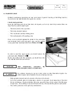
Page 40: ...guide track underneath the bench Picture 12 01Î In order to reach the upper guides you should remove the perforated plate Picture 12 02Î Before proceeding with this operation you should lower the L B and disconnect the main switch After maintenance operations the protection plate must be repositioned For ordinary cleaning do not use water petrol or other flammable liquids Use cloths or paper and e...

Page 41: ...atic Diagram cap 7 Overall dimensions drawing cap 14 We advise the operator that it is not possible to provide drawings or information about all the component parts of this manual The manufacturer will Undertake a more detailed test at his own premises or at Assistance Network s workshop Be at Customer s disposal in order to reply to any questions concerning all the components in order to grant th...

Page 42: ...INSTRUCTION MANUAL Issue 08 2004 Pag 40 42 14 OVERALL DIMENSIONS DRAWING ...

Page 43: ... disposal category or recycling provided by the Law Dismount and separate the equipment components in homogeneous parts according to their classification Collect the oil from the hydraulic system avoiding to dispel it into the soil and deliver it to the local board responsible for its collection and disposal The operator is directly responsible for the above operations according to the Legislation...

Page 44: ...INSTRUCTION MANUAL Issue 08 2004 Pag 42 42 ISTRUCTIONS FOR USE OF 10 TON PULLING BRACKET USE THE A41798 LEVER ONLY IN THE 3 HOLE AS SHOW IN DIAGRAM ABOVE Rif D456 1 ...

Page 45: ...tà GLOBALJIG INTERNATIONAL S r l Tutti i diritti sono riservati Via Aurelia Ovest Km 383 54100 MASSA MS ITALY Tel 39 0585 8364 Fax 39 0585 833880 info globaljig com www globaljig it No part of this document may be reproduced or translated to other languages without written permission from GLOBALJIG INTERNATIONAL S r l All rights reserved ...

Page 46: ...Via Aurelia Ovest Km 383 54100 MASSA MS ITALY Tel 39 0585 8364 Fax 39 0585 833880 info globaljig com www globaljig it ...

Reviews: