INSTRUCTION MANUAL
Issue.
08 / 2004
Pag.
39 - 42
WARNING
13.
REPAIR/ COMPONENTS AND SPARE PARTS
13.1.
REPAIR
PROBLEM POSSIBLE
CAUSE SOLUTION
The lifting bench does not go
up or down
–
Power current fuse (F1) or
transformer fuses (F2/F3)
damaged.
–
Limit switch for the up-
stroke damaged or with no
connection.
–
Damage t the electric or
hydraulic plant.
–
Replacement of the
damaged fuses.
–
Restore the connection or
replace the limit switch.
–
Call the technician.
13.2.
COMPONENTS AND SPARE PARTS
The documentation of this chapter concerns the diagrams and the drawings described in the
following chapters:
–
Electrical Diagram
cap.7
–
Hydraulic Diagram
cap.7
–
Pneumatic Diagram
cap.7
–
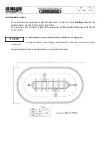
Overall dimensions drawing
cap.14
We advise the operator that it is not possible to provide drawings or information about all the
component parts of this manual. The manufacturer will:
–
Undertake a more detailed test at his own premises or at Assistance Network’s workshop.
–
Be at Customer’s disposal in order to reply to any questions concerning all the components, in
order to grant the correct functioning of the equipment.
The electrical and hydraulic components will be replaced only after manufacturer’s check in order
to determine the cause of the damage.
In case of replacement or assistance, the customer should contact the authorised
local distributor.
The manufacturer is not responsible for injury to people or damage happened during repair carried out
outside manufacturer’s premises or by non authorised staff.
Summary of Contents for Super Rotax
Page 2: ...USERS MANUAL Year of Manufacture ...
Page 21: ...INSTRUCTION MANUAL Issue 08 2004 Pag 19 42 7 1 1 ELECTRICAL PLANT DIAGRAM ...
Page 22: ...INSTRUCTION MANUAL Issue 08 2004 Pag 20 42 7 1 2 HYDRAULIC PLANT DIAGRAM ...
Page 23: ...INSTRUCTION MANUAL Issue 08 2004 Pag 21 42 7 1 3 PNEUMATIC PLANT DIAGRAM ...
Page 42: ...INSTRUCTION MANUAL Issue 08 2004 Pag 40 42 14 OVERALL DIMENSIONS DRAWING ...


