


INSTRUCTION MANUAL
Issue.
08 / 2004
Pag.
6 - 42
4.
FREIGHT AND UNPACKING
4.1.1
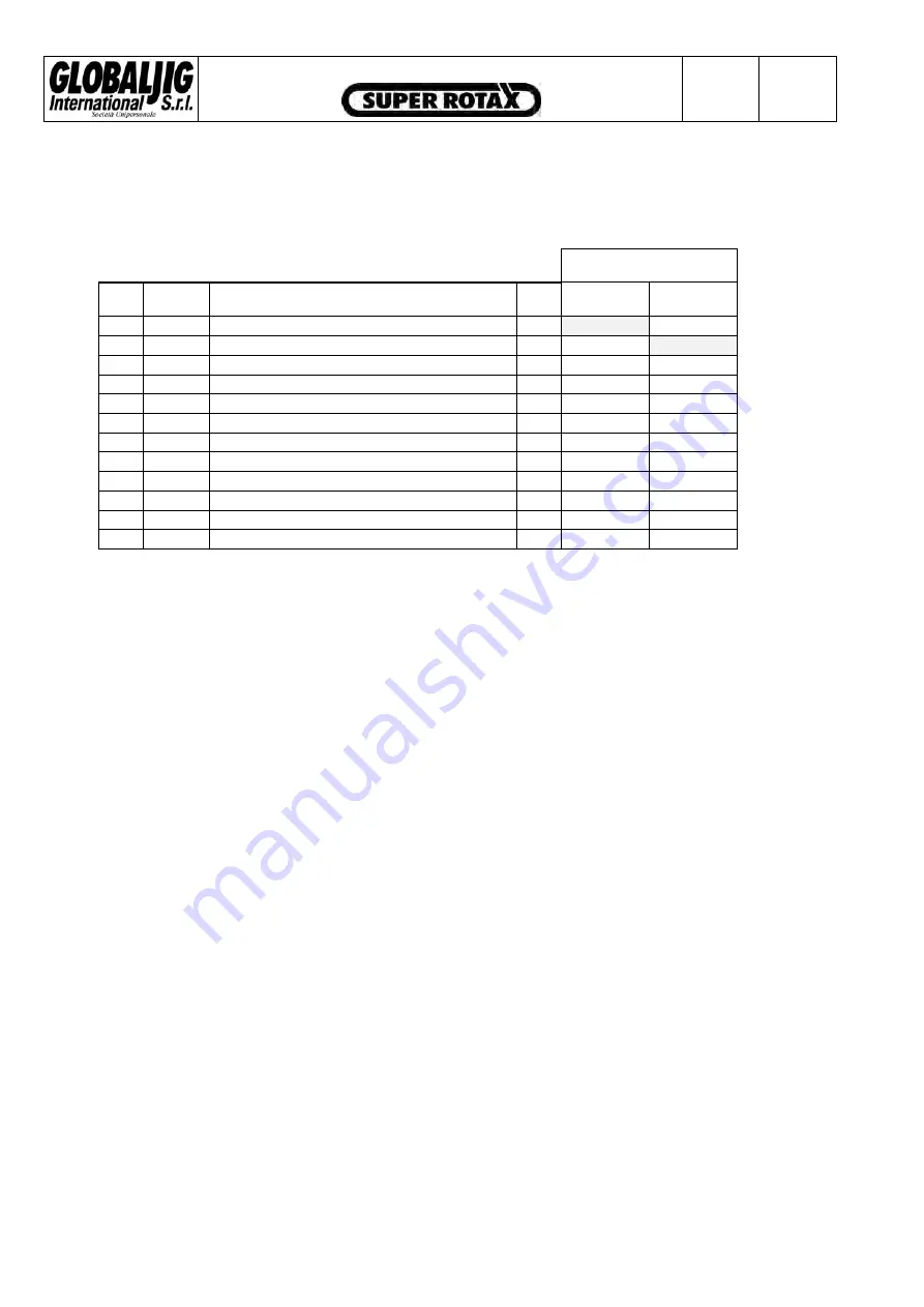
TECHNICAL DATA FOR TRANSPORTATION
GROSS WEIGHT [ kg ]
POS.
CODE
DESCRIPTION
Q.TY
4m 5m
01
E118
Wooden box containing Globaljig System
1
750
02
E119
Wooden box containing Globaljig System
1
670
03
D495
Frame with lift
1
//
2470
04
D496
Frame with lift
1
2250
//
05
D497
Fixed pulling arm
1
370
370
06
D498
Articulated pulling arm
1
410
410
07
E121
Wooden box containing MacPherson
1
90
90
08
E409
Side r ramps
1
190
220
09
D475
Axle crossbeam
1
60
60
10
D211
Electrical winch
1
30
30
11 E418
Trolley
1
70
70
12 E680
Control
unit
1
120
120
GLOBALJIG INTERNATIONAL. srl
grants the quality of the packaging material and the best
procedure concerning the correct location of the goods inside the packages.
All operations of loading and unloading packages, must be carried out using specific procedures
and methods as required by Health and Safety Regulations.
The assigned staff must wear the necessary protective clothing.
GLOBALJIG INTERNATIONAL. srl desclaims all responsibility for damage to people and/or
objects caused when not observing the warnings, the procedures and recommendations during
delivery, loading and handling.
4.1.2
PACKAGE CHECKING
With reference to the standard supply conditions, the transportation of the goods is always at
consignee’s risk, if not otherwise agreed .
Check at sight the delivered goods in the presence of the staff who made the transportation:
•
The quantity of the packages.
•
That no packge has been damaged or broken
•
The presence of condensation or water inside the packages
It is very important to make this first check because the manufacturer will not accept
responsibility for any damage caused during carriage.
Summary of Contents for Super Rotax
Page 2: ...USERS MANUAL Year of Manufacture ...
Page 21: ...INSTRUCTION MANUAL Issue 08 2004 Pag 19 42 7 1 1 ELECTRICAL PLANT DIAGRAM ...
Page 22: ...INSTRUCTION MANUAL Issue 08 2004 Pag 20 42 7 1 2 HYDRAULIC PLANT DIAGRAM ...
Page 23: ...INSTRUCTION MANUAL Issue 08 2004 Pag 21 42 7 1 3 PNEUMATIC PLANT DIAGRAM ...
Page 42: ...INSTRUCTION MANUAL Issue 08 2004 Pag 40 42 14 OVERALL DIMENSIONS DRAWING ...


