background image

20

EN

Table of 

contents

GENERAL INFORMATION ON SAFETY AND INSTALLATION 
ENVIRONMENTAL PROTECTION
TECHNICAL SPECIFICATION 
INSTALLATION AND OPERATION
PREPARATION BEFORE HOOD INSTALLATION
HOOD INSTALLATION
POWER SUPPLY CONNECTION
CLEANING AND MAINTENANCE
CARBON FILTER
ANTI-GREASE FILTER 
SETTINGS
IN CASE OF PROBLEMS 
ENERGY LABEL
REDUCING THE IMPACT OF COOKING ON THE ENVIRONMENT
SERVICE AND MAINTENANCE
TROUBLESHOOTING
LED STRIP REPLACEMENT 
WARRANTY

22
23
24

24-25

26

27-30

31
31
31
32

32-33

33
34
34

34-35
35-36

36

36-37

Summary of Contents for Alario 60

Page 1: ...kcja monta u i u ytkowania EN Operating and installation instructions DE Gebrauchs und Montageanleitung PL Okap kuchenny do zabudowy EN Built in range hood DE Einbau Dunstabzugshaube Alario Alario 60...

Page 2: ...POD CZENIE ELEKTRYCZNE CZYSZCZENIE I KONSERWACJA FILTR W GLOWY FILTR PRZECIWT USZCZOWY STEROWANIE PRAC OKAPU CO ROBI W RAZIE NAPOTKANIA PROBLEMU ETYKIETA ENERGETYCZNA SPOSOBY ZMNIEJSZENIA WP YWU PROC...

Page 3: ...jej zachowanie aby m c z niej skorzysta w ka dej chwili Zesp GLOBALO Dla zapewnienia Pa stwu maksymalnego bezpiecze stwa w u ytkowaniu zakupionego urz dze nia najwa niejsze tre ci niniejszej instrukcj...

Page 4: ...wo zapali Zasysane powietrze przez okap nie mo e by odprowadzane do kana u kominowego s u cego do odprowadzania spalin z urz dze spalaj cych gaz lub inne paliwo nie dotyczy to okap w z obiegiem zamkni...

Page 5: ...ektrycznego i elektronicznego oraz baterii Prowadz cy punkty zbi rki w tym lokalne punkty zbi rki sklepy oraz gminne jednostki tworz odpowiedni system umo liwiaj cy oddanie tego sprz tu oraz baterii j...

Page 6: ...IE ZAGI K TY ZAGI NIE POWINNY BY WI K SZE NI 90 STOPNI NIE ZALECA SI STOSOWANIA ZMIAN PRZEKROJU PRZEWODU WI KSZEGO NA MNIEJSZY NP WYLOT POWIETRZA 15 CM NA WYLOT POWIETRZA 12 CM ZADBAJ ABY W POMIESZCZE...

Page 7: ...trukcji obs ugi urz dzenia grzewczego podana jest wi ksza od leg o ni wskazana powy ej dostosuj si do takich wskaza Monta okapu przedstawiony jest na rysunkach Rys 5 Rys 12 W trakcie jego przeprowa dz...

Page 8: ...ych prac Sprawd czy w pobli u strefy montowania okapu znajduje si gniazdko wtykowe i czy mo na pod czy okap do przewodu wentylacyjnego odprowadzaj cego opary na zewn trz Sprawd czy w miejscach w kt ry...

Page 9: ...rzygotuj szafk do monta u okapu wycinaj c otw r w spodzie szafki zgodnie z rysunkiem Rys 5 2 Wymontuj filtr aluminiowy przeciwt uszczowy Rys 6 min 510 max 530 min 20 600 265 800 min 710 max 751 min 20...

Page 10: ...A 3 Wywier cztery otwory 3 mm nieprzelotowe i umie w nich wkr ty 4 Zawie dwa k towniki monta owe na wkr tach i zamontuj okap przykr caj c sze rub imbusowych 150 X 54 X 276 x4 3 mm 4 2x16 7 mm X min 20...

Page 11: ...11 PL x6 M5x12 Rys 9 5 W celu regulacji po o enia okapu ustaw go tak aby jego dolny panel przylega do spodu szafki poprzez regulacje elementem A nast pnie dokr wkr ty rubokr tem Rys 10 A A...

Page 12: ...12 PL 6 Zamontuj filtr przeciwt uszczowy 7 Pod cz rur do kr ca silnika Rys 11 Rys 12...

Page 13: ...j agodne rodki myj ce Nie u ywaj rodk w ciernych Czyszczenie okapu wykonuj przynajmniej raz w miesi cu lub co 35 godzin pracy okapu Do mycia okapu w adnym wypadku NIE U YWAJ RODK W NA BAZIE ALKOHOLU E...

Page 14: ...za plus silnik w cza si na max stopniu pr dko ci 1 2 3 4 3 5 6 FILTR PRZECIWT USZCZOWY Okap jest wyposa ony w filtr aluminiowy kt ry cz ciowo zatrzymuje cz stki t uszczu pocho dz ce z gotowania Mo esz...

Page 15: ...zpiecznik termiczny osi gnie w a ciw temperatur i ponownie w cz okap Upewnij si e wtyczka jest w czona do sieci Wyjmij wtyczk sieciow aby zrestartowa urz dzenie do stanu wyj ciowego Odczekaj oko o 15...

Page 16: ...zczeniami wynosi max 35h pracy okapu Dbaj o dro no przewod w wentylacyjnych Zawsze ustawiaj poziom pracy turbiny podczas gotowania na minimalny bieg kt ry pozwoli na usuni cie opar w przy aktualnej in...

Page 17: ...czno wyczyszczenia lub wymiany filtra przeciwt uszczowego Naci nij i przytrzymaj przez ok 6s pole na panelu dotykowym Umyj filtr lub wymie na nowy Wy wietlacz pokazuje jedynie znak minus oraz kropka w...

Page 18: ...Filtr przeciwt uszczowy nale y umy lub wymieni na nowy Filtr w glowy je li wyst puje nale y wymieni na nowy Nie wieci jeden lub wi cej punkt wietlny Przepalona ar wka halogenowa ledowa ar wk nale y wy...

Page 19: ...ODZENIA MECHANICZNE KT RY MIMO TO ZOSTA ZAMONTOWANY NIE PODLEGA WYMIANIE PRZED MONTA EM OKAPU NALE Y GO ROZPAKOWA DOKONA DOK ADNYCH OGL DZIN POWIERZCHNI ORAZ SPRAWDZI KOMPLETNO WYPOSA ENIA W CELU ZIDE...

Page 20: ...BEFORE HOOD INSTALLATION HOOD INSTALLATION POWER SUPPLY CONNECTION CLEANING AND MAINTENANCE CARBON FILTER ANTI GREASE FILTER SETTINGS IN CASE OF PROBLEMS ENERGY LABEL REDUCING THE IMPACT OF COOKING ON...

Page 21: ...ly accessible place so that you can consult it at any time GLOBALO team In order to ensure the maximum safety of the device the most important information has been marked with the following symbol THE...

Page 22: ...eep frying overheated fat can easily ignite The air sucked in by the hood must not be discharged into a flue pipe used for exhaust fumes from appliances burning gas or other fuels this does not apply...

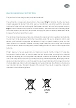
Page 23: ...ectrical and electronic equipment and batteries if any to special collection points for such items Operators of collection facilities including local collection points shops and municipal units must h...

Page 24: ...NDING OF THE DUCT SHOULD BE LIMITED TO MINIMUM THE ANGLES SHOULD NOT EXCEED 90 COMBINING DUCTS WITH DIFFERENT CROSS SECTIONS IS NOT RECOMMENDED E G 15 CM WITH 12 CM ENSURE THAT THE SIZE OF THE SUCTION...

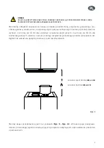
Page 25: ...ooker manual indicates a greater distance than specified above follow the instructions in the cooker manual Installation of the product is shown in Figures 5 12 During installation follow the general...

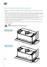
Page 26: ...ments Check whether there is a socket near the hood installation space and whether it is possible to connect the hood to a ventilation duct for fume extraction Make sure there are no lines of electri...

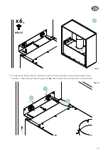
Page 27: ...et where the hood is to be installed by cutting a hole in the bottom of the cabinet as shown in the figure Fig 5 2 Remove the aluminium anti grease filter Fig 6 min 510 max 530 min 20 600 265 800 min...

Page 28: ...3 Drill four 3mm blind holes and insert screws Fig 8 Fig 7 4 Place two angle brackets on the screws and mount the hood by screwing in six Allen screws x2 x6 A A 150 X 54 X 276 x4 3 mm 4 2x16 7 mm X mi...

Page 29: ...EN Fig 9 5 To adjust the hood position place the hood so that the bottom panel leans against the drawer s underside by adjusting element A then tighten the screws with a screwdriver Fig 10 x6 M5x12 A...

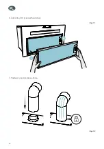
Page 30: ...30 EN 6 Install the grease filter 7 Connect the duct to the motor connection Fig 11 Fig 12...

Page 31: ...tergents for cleaning Do not use abrasive cleaning products The hood should be cleaned at least once a month or every 35 hours of operation DO NOT USE ALCOHOL BASED CLEANING AGENTS Inox parts should b...

Page 32: ...eed level Switching the lighting on and off To turn the hood lighting on press Pressing the button again turns the lighting off 2 3 2 4 1 4 5 ANTI GREASE FILTER The hood is equipped with an aluminium...

Page 33: ...30 minutes until the temperature returns to normal then switch the hood on again Make sure that the plug is inserted in the socket Remove the plug to restart the device Wait for about 15 20 seconds an...

Page 34: ...ith lids while cooking Keep the aluminium filters clean the recommended cleaning schedule for the filter is at least once every 35 hours Keep the ventilation ducts unobstructed Always set the turbine...

Page 35: ...for approx 6s the button on the panel Clean the filter or replace it with a new one The display only shows the sign minus and dot in the lower right corner the hood does not start when switched on Th...

Page 36: ...r After adjusting the position of the hood vertically and hori zontally tighten all the mounting screws applies to range hoods with touch control If after following the above mentioned guidelines the...

Page 37: ...Y MISSING COMPONENTS OR DAMAGE ANY VISIBLE EXTERNAL DAMAGE CLAIMED AFTER INSTAL LATION IS EXCLUDED FROM THE WARRANTY GLOBALO MAX SHALL NOT BE HELD LIABLE FOR DAMAGE CAUSED DIRECTLY OR INDIRECTLY BY PE...

Page 38: ...DER DUNSTABZUGSHAUBE ELEKTRISCHER ANSCHLUSS REINIGUNG UND WARTUNG KOHLEFILTER FETTFILTER STEUERUNG DER DUNSTABZUGSHAUBE WAS IST BEI PROBLEMEN ZU TUN ENERGIEETIKETT METHODEN ZUR REDUZIERUNG DER UMWELTE...

Page 39: ...diese Gebrauchs und Montageanleitung gut aufzubewahren damit Sie jederzeit auf sie zugreifen k nnen GLOBALO Team Um Ihnen maximale Sicherheit bei Gebrauch des von Ihnen gekauften Ger tes zu gew hrlei...

Page 40: ...gshaube angesaugte Luft darf nicht in die Abgasleitung ber die bei der Verbrennung von Gas oder anderen Brennstoffen erzeugte Abgase abgeleitet werden eingeleitet dies gilt nicht f r Dunstabzugshauben...

Page 41: ...rische und elektronische Ger te und Batterien zu bergeben Die Betreiber von Abfallssammelstellen darunter auch von lokalen Abfallssammelstellen Gesch ften und kommunalen Abfallssammelstellen bilden ei...

Page 42: ...AD BETRAGEN ES WIRD NICHT EMPFOHLEN VON EINEM LEITUNGSDURCHMESSER IN EINEN ANDEREN ZU WECH SELN VON EINEM H HEREN DURCHMESSER IN EINEN GERINGEREN DURCHMESSER Z B VON EINEM LUFTAUSLAUF 15 CM IN EINEN L...

Page 43: ...t in der Gebrauchsanleitung des jeweiligen Herdes ein Abstand angegeben der h her als der hier genannter Abstand ist ber cksichtigen Sie solche Vorgaben Die Dunstabzugshaubemontage ist auf den Abbildu...

Page 44: ...Gegenst nde Pr fen Sie ob in der N he der Dunstabzugshaubemontagezone eine Steckdose vorhanden ist und ob die Dunstabzugshaube an eine L ftungsleitung die D nste nach au en ableitet ange schlossen wer...

Page 45: ...e einen Schrank zur Montage der Dunstabzugshaube indem Sie gem der Zeich nung eine Bohrung im Schrankboden herstellen Abb 5 2 Bauen Sie den Aluminium Fettfilter aus Abb 6 min 510 max 530 min 20 600 26...

Page 46: ...er von 3 mm her und legen Sie Bohrschrauben darin Abb 8 Abb 7 4 H ngen Sie zwei L Montageprofile auf den Bohrschrauben auf und bauen Sie die Dunstabzugshaube ein indem Sie sechs Imbussschrauben anwend...

Page 47: ...shaube einzustellen muss sie so positioniert werden dass ihre Unterseite b ndig mit dem Boden des Schranks abschlie t indem Punkt A eingestellt wird anschlie end ziehen Sie die Bohrschrauben mit einem...

Page 48: ...48 DE 6 Den Fettfilter einsetzen 7 Verbinden Sie das Rohr mit dem Motorstutzen Abb 11 Abb 12...

Page 49: ...enden Sie keine Schleifmittel Reinigen Sie die Dunstabzugshaube zumindest einmal im Monat oder immer nach 35 Betriebsstunden Zur Reinigung der Dunstabzugshaube VERWENDEN SIE AUF KEINEN FALL REINIGUNGS...

Page 50: ...ann auch dazu beitragen dass ein Brand entsteht STEUERUNG DER DUNSTABZUGSHAUBE TASTEN AUF DER DUNSTABZUGSHAUBE ODER FERNBEDIENUNG LED Anzeige Die ausgew hlte Drehgeschwindigkeitsstufe 1 2 3 4 wird mit...

Page 51: ...et wur de Zu diesem Zweck schalten Sie das Ger t aus und warten Sie ca 20 30 Minuten ab bis die Thermosicherung eine korrekte Temperatur erreicht und dann schalten Sie die Dunstabzugs haube wieder ein...

Page 52: ...erbrauch zu reduzieren kochen Sie immer in abgedecktem Geschirr Halten Sie die Aluminiumfilter sauber die zu empfehlende Betriebszeit eines Aluminiumfilters zwischen den Reinigungsvorg ngen betr gt ma...

Page 53: ...ell ___________________ Serien Nr ___________________ Diese Informationen sind dem Datenschild zu entnehmen Er ist im Inneren der Dunstabzugshaube vorhanden und ist zu sehen nachdem Sie das Metallfilt...

Page 54: ...altfl che mit einem Plussymbol zu bet tigen und dann ca 10 Sekunden lang gedr ckt zu halten oder die Dunstabzugshaube ist auszuschalten Bei der vierten Drehgeschwindig keitsstufe blinkt die Ziffer 4 a...

Page 55: ...Ger tes ACHTUNG WAREN MIT MECHANISCHEN SCH DEN DIE DENNOCH INSTALLIERT WURDEN WERDEN NICHT AUS GETAUSCHT VOR MONTAGE DER DUNSTABZUGSHAUBE IST SIE AUSZUPACKEN DIE OBERFL CHE GE NAU ZU BERPR FEN UND DI...

Page 56: ...a GLOBALO ul Mak w 10 38 500 Sanok Polska Poland Polen Tel 48 13 49 27 560 https globalo pl e mail biuro globalo pl Serwis Service Kundendienst Tel 48 13 49 27 560 wew 3 Kom 48 609 055 660 e mail serw...

Reviews: