G l o b a l s t a r M C M - 4 e
C A S C A D E D M C M - 4 e S E T - U P
1
Cascaded MCM-4e Set-up
1.
Follow instruction above in Section 3.5 MCM-4e Installation for both MCM-4e units.
2.
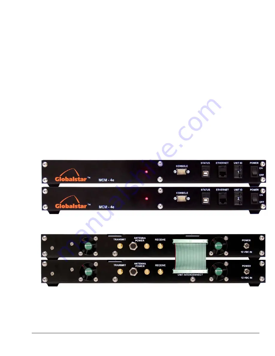
Install the second MCM-4e in its preferred location within 12 inches of the first MCM-4e unit. (see
figure 4-1)
3.
At the rear panel of both MCM-4e units Install the Cascade Cable to the “Unit Interconnect”
Connectors as shown in Figure 4.2.
4.
Set the “Thumbwheel Switch” to position 1 on the primary MCM-4e Unit.
5.
Set the “Thumbwheel Switch” to position 2 on the secondary MCM-4e Unit.
6.
Route Ethernet Cable to planned locations of remote client equipment from the Primary MCM-4e
unit. The Ethernet port on the secondary MCM-4e unit must be left open.
Do not connect an
Ethernet cable to the secondary unit while in cascade operations.
7.
Turn on power to both units. Primary unit will auto configure both units to use all 8 modems after
a short initialization time(30-45 seconds)
Multi Channel Modem (MCM- 4e) Cascaded Set-up Front Panel
Figure 0-1 MCM-4e Front Panel
Multi Channel Modem (MCM- 4e) Cascaded Set-up Rear Panel
Figure 0-2 MCM-4e Rear Panel
Summary of Contents for MCM-4
Page 25: ...G l o b a l s t a r M C M 4 e D R A W I N G S 2 ANCT0601 021 MCM 4e Parts List ...
Page 26: ...G l o b a l s t a r M C M 4 e D R A W I N G S 3 ANCT0601 021 MCM 4e Front and Rear Panel ...
Page 27: ...G l o b a l s t a r M C M 4 e D R A W I N G S 4 ANCT0601 021 MCM 4e Top and Side View ...
Page 28: ...G l o b a l s t a r M C M 4 e D R A W I N G S 5 ANCT0601 021 MCM 4e Top View Cover Removed ...
Page 32: ...G l o b a l s t a r M C M 4 e D R A W I N G S 9 ANCT0601 021 MCM 4e RF Cable Diagram ...


