background image

4 ·

· 5

MANUAL | VA10J&X | VS10C | VA10C | ATEX certified

MANUAL | VA10J&X | VS10C | VA10C | ATEX certified


»

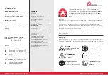
To check that the air motor is designed for use 
in hazardous applications read the air motor 
label: 


»

Hazardous zone


»

Hazardous category


»

Equipment group


»

Temperature class


»

Maximum surface temperatures


»

Check the air motor before installation and 
operation to see if it’s not damaged.


»

Any products that are driven by the air motor 
must meet appropriate ATEX approval as well 
to be used in a hazardous area.


»

The air motor should be connected to the 
earth with a maximum earth resistance of 
1Mohm. The motor can be earthed by con-
necting the motor to a base plate/gearbox 
etc.


»

The ambient temperature range of the motor 
(-20°C to +60°C) should be observed at all 
times. 


»

When mounting the engine on a construction 
or when something is mounted on the shaft of 
the air motor. Make sure that the alignment is 
straight to prevent too much force on the shaft.


»

An air filter should be placed in the airline 
with at least 64 micron near the air motor.


»

Clean surface of air motor unit thoroughly of 
all dustproofing products, contaminants and 
other impurities. Do this outside the hazardous 
area or clean only with a damp cloth. 


»

A lubricator must be placed inside the main 
airline near the motor. The lubricator unit 
should have a bowl with enough oil for 
operation and should allow the user to control 
the amount of oil drop per minute going to 
the motor. 


»

Check airline oil every time before starting. 
Air motor should be supplied with oil of a 
viscosity of 32. This type of oil is flammable at 
a temperature of 218°C.


»

Air supply to the motor should always be 
taken from non-hazardous area.


»

In case the motor is exposed to high vibrati-
ons during operation and when not in ope-
ration, please contact the manufacturer. High 
vibrations might lead to increased inspection 
interval of the bearings. 


»

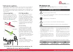
Mounting positions

It’s important that no dust or debris can 
accumulate at the output shaft. This may 
damage the shaft seal. If the motor is 
built in a closed system or construction 
so that no dust or debris can get in 
contact with the output shaft the air 
motor can be used in any orientation. 
If the motor is used is such way that the 
output shaft is in contact with explosive 
environment the mounting position 
is limited from horizontal to vertical 
downwards. It is not allowed for the 
shaft to point in any angle upwards.

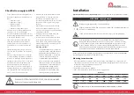
Checklist to comply to ATEX:

WARNING: POTENTIAL ELECTROSTATIC CHARGING HAZARD 
Before use clean only with damp cloth.

Installation

Correct installation is your responsibility!

 Make sure you have the proper installation conditions.

Install proper guard around the output shaft if needed.

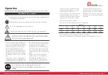
WARNING - Injury hazard

Wear eye protection: Airflow from product may contain solid or liquid materials that can 
result in eye or skin damage.

Failure to follow these instructions can result in serious injury or property damage.

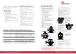
It’s important that no dust or debris can accumulate at the output shaft. This may 
damage the shaft seal. If the motor is built in a closed system or construction so that 
no dust or debris can get in contact with the output shaft the air motor can be used 
in any orientation. If the motor is used is such way that the output shaft is in contact 
with explosive environment the mounting position is limited from horizontal to vertical 
downwards. It is not allowed for the shaft to point in any angle upwards.

In order to guarantee the maximum performance and service life of these motors it is essential that 
the  following points are strictly observed and obeyed.

Mounting to construction 


»

Mount the unit to the construction. Care should be taken, when fitting drive components to the 
shaft, that excessive force is not used. This will upset the shaft alignments which has been kept to a 
minimum in order to give high motor performance. 


»

Use the proper sized fasteners. 


»

Axial loads must be kept to a minimum.


»

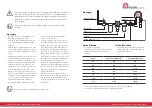
Max. radial load midway along shaft as shown in graph below:

Air motor

V1

V2

V4

V6

V8

V10

V12

LBF

4

90

40

70

140

400

157

N

18

400

170

300

620

1.750

700

Ground the motor to the earth with a maximum earth resistance of 1Mohm.

Summary of Contents for VA10C

Page 1: ...nl Manual GLOBE Vane Air Motor VA10J X VS10C VA10C ATEX certified II 2G Ex h IIC T4 Gb II 2D Ex h IIIC T135 C Db GLOBE Airmotors Boerhaaveweg 9 1 1 NL 2408 AD Alphen a d Rijn Tel 31 172 426 608 info globe benelux nl ...

Page 2: ...dead or severe injuries Dangerous situation Possible consequence damage to the drive of the environment Wear hearing protection Wear eye protection Important instructions on protection against explosion Hazard Situation Possible consequences slight or mild injuries APPROVALS ATEX CERTIFICATION II 2G Ex h IIC T4 Gb II 2D Ex h IIIC T135 C Db The GLOBE vane air motors are ATEX certified according to ...

Page 3: ...may damage the shaft seal If the motor is built in a closed system or construction so that no dust or debris can get in contact with the output shaft the air motor can be used in any orientation If the motor is used is such way that the output shaft is in contact with explosive environment the mounting position is limited from horizontal to vertical downwards It is not allowed for the shaft to poi...

Page 4: ...d particles and ISO 8473 1 2010 class 3 for water For the most efficient power and control of speed all valves and the airlines should be the same size as the air connections of the motor If the valves airlines and other con nections have a longer distance than 2m 6 feet of the motor we advise one size bigger Before final connection to the motor clean the compressed air connection with low pressur...

Page 5: ...nternal heat that may cause motor damage The starting torque is less than the running torque The starting torque will vary depen ding on the position of the vanes in relation to the air intake port when the motor is being started During operation be aware if unfamiliar sounds or vibrations occur Stop the unit immediately and investigate the source In case that the motor is exposed to high vibratio...

Page 6: ...ed Torque 0 100 120 140 160 180 200 220 240 1 2 3 4 5 6 Rotation speed Torque Pressure regulation Air flow regulation For optimal power and speed control we advise to use the combination of pressure and air flow regulation Pressure regulation Air flow regulation optional Supply air throttling Exhaust air throttling 1 Pressure regulation With pressure regulation the output power can be adjusted Whe...

Page 7: ...Assembly details All parts must be clean and it is recommended that new oilseals and blades are fitted as a matter of course Press all bearings fully home into their respective covers pressing only on the outer track to prevent damaging the bearings On V1 V2 V4 motors fit oilseal retaining circlip and a new oilseal Cs Rotor Shaft Assy Ejection ring Rear cover Bearing Bearing support V1 Motor Cs Ro...

Page 8: ...6 790 037 Flange D100 1 07 790 008 Cover Plate 1 08 Gasket 1 799 910 09 Gasket 2 799 910 09A 1 Gasket 1 799 910 09A 2 Gasket 1 799 910 09A 3 Gasket 1 799 910 10 790 923 Rotor Shaft Assy 1 11 802 007 Screw 6 12 802 033 Screw 16 13 806 018 Dowel 4 14 807 037 Bearing 1 15 807 019 Bearing 1 16 O Ring 1 799 910 17 Oil Seal 1 799 910 18 809 019 Cap Screw 1 20 811 033 Key 1 21 803 019 Washer 1 799 910 V1...

Page 9: ...1 1 024 Key 1 21 803 019 Washer 16 22 790 007 Seal Housing 1 23 790 015 Base Plate 1 24 809 008 Capscrew 4 799 910 V10 Seal Kit 820 007 Silencer 11 4 1 VS10C NL Vane Air Motor Exploded view with spare parts list Item Part No Description Qty Kit No 01 790 101 Body BSP 1 02 790 002 End Plate 1 03 790 026 Front Cover 1 04 Blades 6 799 915 05 790 006 Ejection Ring 2 06 790 037 Flange D100 1 07 790 008...

Page 10: ...loded view with spare parts list Item Part No Description Qty Kit No 01 790 001 NPT Body 1 02 790 002 End Plate 1 04 Blades 4 799 910 05 790 006 Ejection Ring 2 06 790 018 Flange NEMA 145TC 1 08 Gasket 1 799 910 09 Gasket 2 799 910 09 A1 Gasket 1 799 910 09 A2 Gasket 1 799 910 09 A3 Gasket 1 799 910 10 790 910 Rotor Shaft Assy 1 1 1 802 001 Screw 6 12 802 033 Screw 16 13 806 018 Dowel 4 14 807 037...

Page 11: ...lable for download on globe benelux nl Compact Piston Air Motors Pneumatic Brakes Compact Vane Air Motors Planetary Geared Vane Air Motor Specials Costum Build Radial Piston Air Motors GLOBE Airmotors Boerhaaveweg 9 1 1 NL 2408 AD Alphen a d Rijn Tel 31 172 426 608 info globe benelux nl ...

Reviews: