background image

9

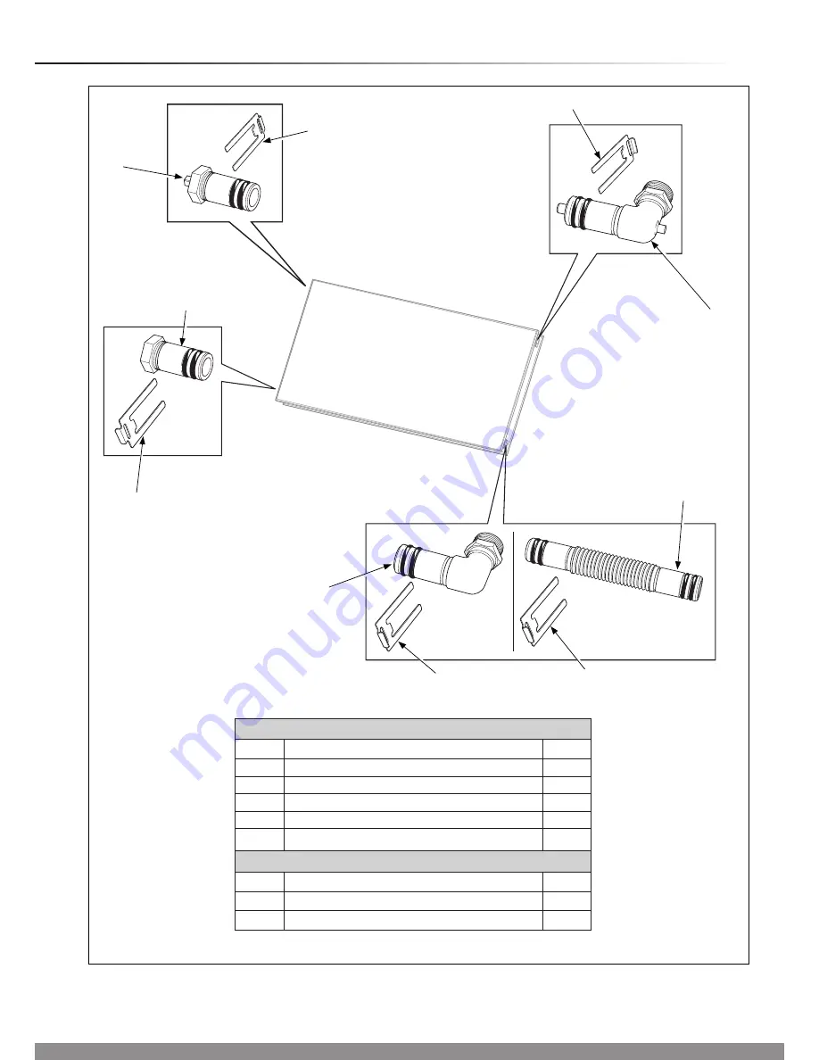
4  Hydraulic Connection Kits

Diagram 4.1

15188

2

1

3

5

5

4

7

5

6

7

Easy fit hydraulic connection set - Kit No. 0020060207
Part

Description

Qty.

1

Upper supply (with probe)

1

2

Return (inlet)

1

3

Lower plug

1

4

Upper plug (with ventilation)

1

5

Securing clip

4

Easy fit hydraulic extension set - Kit No. 0020055175

Part

Description

Qty.

6

Pipe coupling

2

7

Securing clip

4

Summary of Contents for Clearly Solar

Page 1: ...1 www glow worm co uk Solar Thermal Flat Plate Collector Installation Instructions Clearly Solar Horizontal On roof mounting 15 75 SRH 2 3...

Page 2: ...ppropriate Building Regulations The Benchmark Checklist can be used to demonstrate compliance with Building Regulations and should be provided to the customer for future reference Installers are requi...

Page 3: ...ngs 4 Important Information 4 Statutory Requirements 5 Technical Specification 1 6 Technical Data 2 7 Solar Collector and Hydraulic Connection Arrangement 3 8 Hydraulic Connection Kits 4 9 Roof Anchor...

Page 4: ...ion is made without permission in writing by Glow worm Any alteration not approved by Glow worm could invalidate the certification warranty and may also infringe the current issue of the statutory req...

Page 5: ...ng of electrical installations The Health and Safety at Work Act Control of Substances Hazardous to Health COSHH The Current I E E Wiring Regulations The Water Supply water fittings Regulations 1999 o...

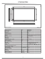
Page 6: ...owing tables and illustrated in the appropriate sections 1 Technical Specification On roof installation components 1 1 On roof mounting With on roof mounting flat collectors are fastened to horizontal...

Page 7: ...eight Dry kg 38 Fluid content l 2 16 Copper pipe connection flat face mm G 3 4 DN16 Insulation thickness mm 40 Max operating pressure bar 10 Glass type Solar safety glass prismatic structure Glass cov...

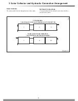
Page 8: ...r arrangements are shown below Hydraulic Connections It is recommended that the hydraulic connections should be made as shown below 1 4 5 1 9 10 Diagram 3 2 15045 6 and up to 10 max Collectors THE HYD...

Page 9: ...draulic connection set Kit No 0020060207 Part Description Qty 1 Upper supply with probe 1 2 Return inlet 1 3 Lower plug 1 4 Upper plug with ventilation 1 5 Securing clip 4 Easy fit hydraulic extension...

Page 10: ...1433 1633 Diagram 5 2 SECURING SCREW ROOF ANCHOR TYPE P B C C B B B A 74 15153 15186 BOTTOM PLATE SECURING SCREW 120 120 1233 120 120 COLLECTOR CLAMP COLLECTOR CLAMP 15408 Total adjustment of collecto...

Page 11: ...of battens and rafters where required please refer to diagram 5 1 and 5 2 for position of brackets If required loosen the securing screw see diagram 5 2 Using a 5mm Allen key release the bottom plate...

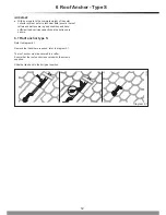
Page 12: ...are in good condition and have sufficient load carrying capacity and the battens are secure 6 1 Roof anchor type S Refer to diagram 6 1 Remove the tiles where required refer to diagram 5 1 The roof an...

Page 13: ...beneath the clamp see diagram 7 2 NOTE The design is symmetrical and does not have a top or bottom IMPORTANT Do not remove the protective film until the system is to be commissioned Move the clamp int...

Page 14: ...with the securing clip Place the next collector on the lower mounting bracket Slide the collector up to the first collector paying attention to the pipe couplings see diagram 7 4 When fully inserted t...

Page 15: ...have been fixed with securing clips All hydraulic connections laid properly The collector sensor has been connected The collectors are connected to a lightning protection device A pressure test carri...

Page 16: ...16 Glow worm Nottingham Road Belper Derbyshire DE56 1JT Because of our constant endeavour for improvement details may vary slightly from those shown in these instructions 0020080932 02 03 09...

Reviews: