0020313973_01 Compact Installation and maintenance instructions
17
6.5.3
Flue Configuration Description
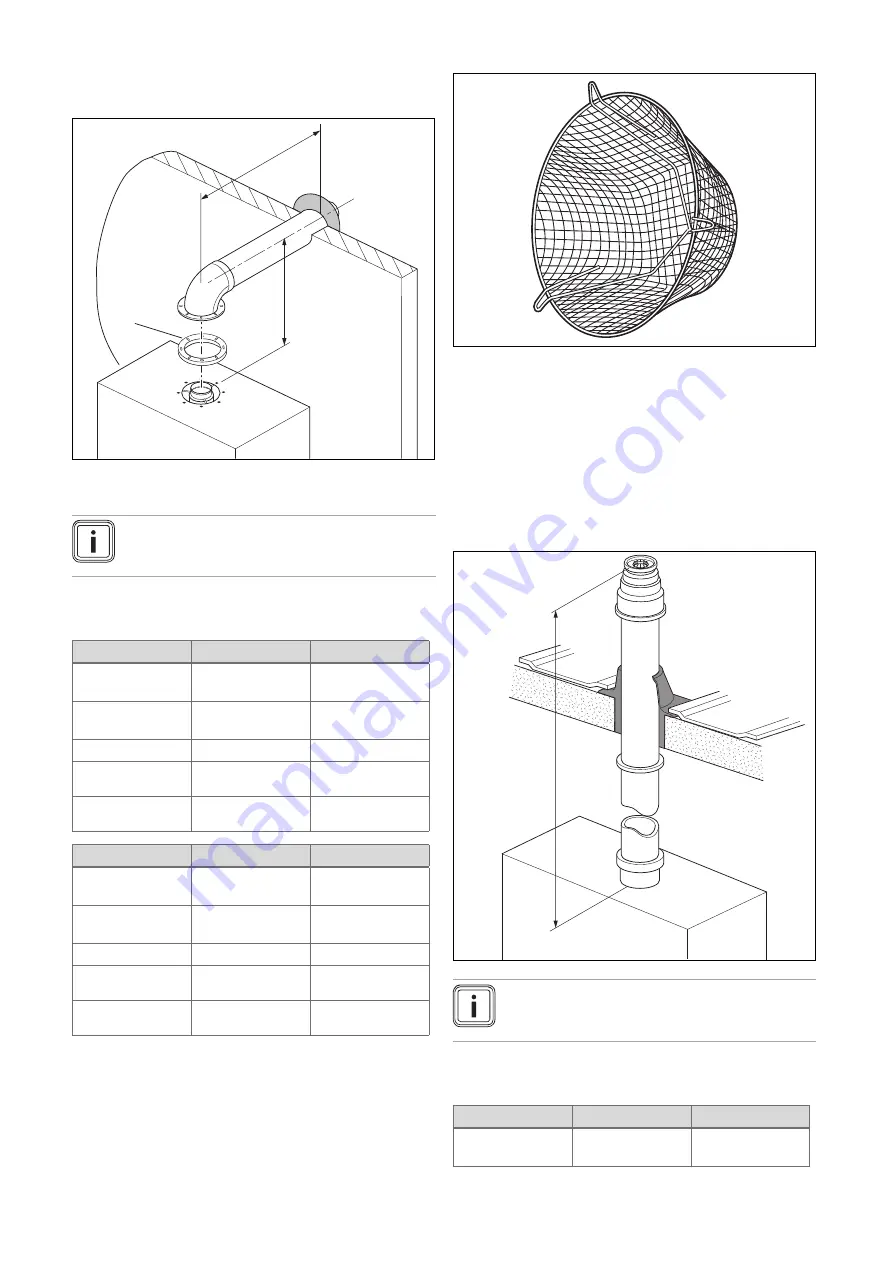
6.5.3.1 Horizontal Concentric Flue
⌀
60/100 mm or
⌀
80/125 mm (C13 type installation)
L
H
1
1
Gasket (fitted)
Note
If the terminal is at less than 1.80 m from the
ground, you must install a terminal protection kit.
Each time an additional 90° bend is necessary (or 2 at 45°),
the length (L) must be reduced (see table below).
⌀
60/100
24c-AS/1
28c-AS/1
Min. length (L)
0.3 m
including 1 elbow
0.3 m
including 1 elbow
Max. length (L)
9 m
including 1 elbow
9 m
including 1 elbow
Max. height (H)
0.63 m
0.63 m
Equivalence to 1
elbow 90°
1 m
1 m
Equivalence to 1
elbow 45°
0.5 m
0.5 m
⌀
80/125
24c-AS/1
28c-AS/1
Min. length (L)
0.3 m
including 1 elbow
0.3 m
including 1 elbow
Max. length (L)
16 m
including 1 elbow
20 m
including 1 elbow
Max. height (H)
2.10 m
2.10 m
Equivalence to 1
elbow 90°
2.5 m
2.5 m
Equivalence to 1
elbow 45°
1 m
1 m
6.5.3.2 Terminal protection
A terminal guard is required if persons could come into con-
tact with the terminal or the terminal could be subject to dam-
age.
If a terminal guard is required, it must be positioned to
provide minimum of 50 mm clearance from any part of the
terminal and be central over the terminal.
The guard should be similar to that shown in the figure.
6.5.3.3 Vertical Concentric Flue
⌀
60/100 mm or
⌀
80/125 mm (C33 type installation)
L
Note
If the terminal is at less than 1.80 m from the
ground, you must install a terminal protection kit.
Each time an additional 90° bend is necessary (or 2 at 45°),
the length (L) must be reduced (see table below).
⌀
60/100
24c-AS/1
28c-AS/1
Min. length (L)
0.3 m
including 1 elbow
0.3 m
including 1 elbow
Summary of Contents for Compact 24c-AS/1
Page 59: ......


