20
Installation and maintenance instructions Compact 0020313973_01
7
Installation
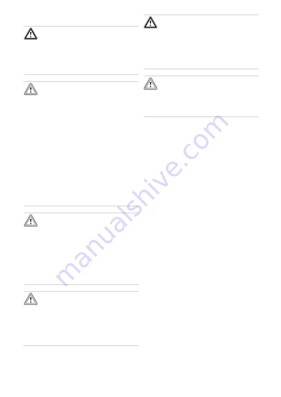
Danger!
Risk of scalding and/or risk of material
damage due to incorrect installation lead-
ing to escaping water.
Mechanical stresses in connection cables
can cause leaks.
▶
Install the connection cables voltage-free.
Caution.
Risk of material damage due to the gas
tightness test.
At a test pressure of >11 kPa (110 mbar), gas
tightness tests may cause damage to the gas
valve.
▶
If, during gas tightness tests, you also
place the gas lines and the gas valve in
the product under pressure, use a max.
test pressure of 11 kPa (110 mbar).
▶
If you cannot limit the test pressure to
11 kPa (110 mbar), close any gas isolator
cocks that are installed upstream from
the product before you carry out the gas
tightness test.
▶
If, during gas tightness tests, you have
closed the gas isolator cock that is in-
stalled upstream of the product, relieve
the gas line pressure before you open this
gas isolator cock.
Caution.
Risk of material damage due to heat trans-
fer during soldering.
The product's base plate is not available as a
spare part. If the base plate is damaged due
to excessive temperatures, the product must
be viewed as a total economic write-off.
▶
You can solder the connectors if they
have not been secured to the service
valves. Once they have been secured,
this is no longer possible.
Caution.
Risk of material damage caused by
residues in the pipelines.
Welding remnants, sealing residues, dirt or
other residues in the pipelines may damage
the product.
▶
Flush the heating installation thoroughly
before installing the product.
Warning.
Risk of adverse health effects caused by
impurities in the potable water.
Sealing residues, dirt or other residues in the
pipelines may adversely affect the quality of
the potable water.
▶
Flush all of the hot and cold water pipes
thoroughly before you install the product.
Caution.
Risk of material damage caused by
changes to the pipes that have already
been connected.
▶
Only bend connection pipes if they have
not yet been connected to the product.
7.1
Prerequisites
7.1.1
Carrying out basic preparation for the
installation
1.
Make sure that the existing gas meter is capable of
passing the rate of gas supply required.
2.
Consider the maximum heat output given in DHW
mode.
3.
Install the connection pipes such that they are free
from mechanical stress.
4.
Ensure that the volumetric capacity of the integrated
expansion vessel is sufficient for the system volume.
–
If the volumetric capacity of the expansion vessel
is insufficient, install an additional expansion vessel
as close to the product as possible
5.
Insulate bare pipes exposed to environmental influ-
ences to protect them from frost using suitable insula-
tion material.
6.
Flush out the supply pipes thoroughly prior to installa-
tion.
7.
Install a filling device between the cold water pipe and
the heating flow.
8.
Securely connect the product to the water mains. Do
not use a connection hose set for this.
7.1.2
Using the correct gas type
Using the incorrect gas type may cause fault shutdowns in
the product. Ignition and combustion noise may occur in the
product.
▶
Only use the gas type listed on the data plate.
7.1.3
Information on the gas group
In the as-supplied condition, the product is preset for opera-
tion with the gas group indicated on the data plate.
Summary of Contents for Compact 24c-AS/1
Page 59: ......


