24
Installation and maintenance instructions Compact 0020313973_01
–
The combustion air must not be taken from the install-
ation site.
▶
Install the air/flue pipe using the set-up instructions.
7.9
Electrical installation
Only qualified electricians may carry out the electrical install-
ation.
The product must be earthed.
Danger!
Risk of death from electric shock!
Power supply terminals L and N remain live
even if the on/off button is switched off.
▶
Disconnect the product from the power
supply by switching off all power supplies
at all poles (electrical partition with a con-
tact gap of at least 3 mm, e.g. fuse or cir-
cuit breaker).
▶
Secure against being switched back on
again.
▶
Wait for at least 3 minutes until the capa-
citors have discharged.
▶
Check that there is no voltage.
7.9.1
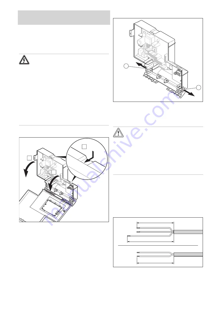
Opening the electronics box
A
B
B
7.9.2
Cable route
230V
24V / eBUS
1
2
1
24-V eBUS cable route
2
230 V cable route
7.9.3
General information about connecting
cables
Caution.
Risk of material damage caused by incor-
rect installation.
Mains voltage at incorrect terminals and plug
terminals may destroy the electronics.
▶
Do not connect any mains voltage to the
eBUS (+/-) and RT 24 V terminals.
▶
Only connect the connection cable to the
terminals marked for the purpose.
1.
Route the connection cable in the cable trunking on the
underside of the product.
2.
Ensure that the grommet is plugged in correctly and
that the cables have been routed correctly.
3.
Ensure that the grommets envelop the connection
cables tightly and with no visible gaps.
4.
Use the strain reliefs.
5.
If required, shorten the connection cables.
-
+
N
L
PE
30 mm
≤
30 mm
≤
40 mm
≤
6.
Strip the flexible ducts as shown in the figure. In doing
so, ensure that the insulation on the individual conduct-
ors is not damaged.
7.
Only strip inner conductors just enough to establish
stable connections.
Summary of Contents for Compact 24c-AS/1
Page 59: ......


