30
Installation and maintenance instructions Compact 0020313973_01
9.6.3
Checking the gas flow rate
The boiler is fitted with a multifunctional automatic gas valve
which ensures that the precise air/gas ratio is provided un-
der all operating conditions. The gas flow rate has been set
during production and does not require adjustment. With the
front casing fitted check the gas flow rate of the boiler as fol-
lows:
▶
Start up the product with the check programme
P.01
.
▶
In addition, ensure that maximum heat can be dissipated
into the heating system by turning up the room thermo-
stat.
▶
Wait at least 5 minutes until the boiler has reached its
operating temperature.
▶
Ensure that all other gas appliances in the property are
turned off.
▶
Measure the gas flow rate at the gas meter.
▶
Compare the measured values with the corresponding
values in the table.
Validity:
Compact 24c-AS/1 (H-GB) OR Compact 24c-AS/1 (P-GB)
Qnw from
the data
plate
H gas in m
³
/h
P gas in m
³
/h
Nom.
+5%
−
10%
Nom.
+5%
−
10%
6.2
0.65
0.68
0.59
–
–
–
8.4
–
–
–
0.34
0.36
0.31
18.8
1.98
2.08
1.78
0.77
0.81
0.69
24
2.53
2.66
2.28
0.98
1.03
0.88
Validity:
Compact 28c-AS/1 (H-GB) OR Compact 28c-AS/1 (P-GB)
Qnw from
the data
plate
H gas in m
³
/h
P gas in m
³
/h
Nom.
+5%
−
10%
Nom.
+5%
−
10%
7.2
0.76
0.80
0.68
0.29
0.30
0.26
24.5
2.58
2.71
2.32
1.00
1.05
0.90
28
2.95
3.10
2.66
1.15
1.21
1.04
Condition
: Gas flow rate not in the permissible range
▶
Check all of the piping and ensure that the gas flow rates
are correct.
▶
Only put the product into operation once the gas flow
rates have been corrected.
Condition
: Gas flow rate in the permissible range
▶
End check programme
P.01
.
▶
Allow the boiler to cool down by allowing pump overrun to
operate for a minimum of two minutes.
▶
Record the boiler maximum gas flow rate onto the
Benchmark gas boiler commissioning checklist.
9.6.4
Checking the gas connection pressure/gas
flow pressure
1.
Temporarily decommission the product. (
2.
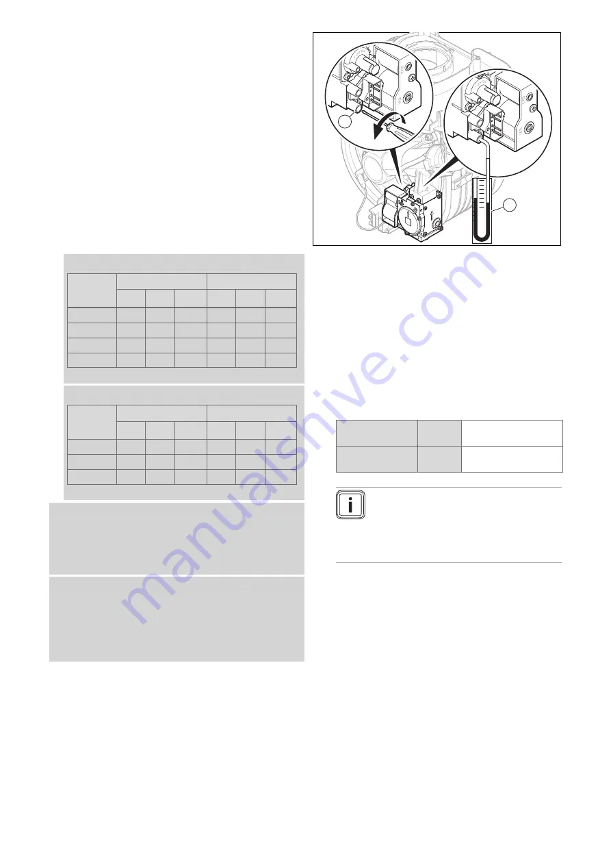
Hinge the electronics box downwards.
2
1
3.
Turn the screw on the gas pressure measuring point
(1)
anti-clockwise.
–
Anti-clockwise (
↺
): Two rotations
4.
Connect a manometer
(2)
to the test nipple
(1)
.
–
Working materials: U tube manometer
–
Working materials: Digital pressure gauge
5.
Hinge the electronics box upwards.
6.
Open the gas stopcock.
7.
Start up the product with check programme
P.01
(in
doing so, set the output to the maximum). (
8.
Measure the gas connection pressure/gas flow pres-
sure against the atmospheric pressure.
Permissible connection pressure
Great
Bri-
tain
Natural gas
H
1.7 to 2.5 kPa
(17.0 to 25.0 mbar)
Liquefied petro-
leum gas
P
2.5 to 4.5 kPa
(25.0 to 45.0 mbar)
Note
The connection pressure is measured at the
gas valve assembly, meaning that the per-
missible minimum value may be 0.1 kPa (1
mbar) lower than the minimum value spe-
cified in the table.
Result 1:
Gas connection pressure/gas flow pressure in the per-
missible range
▶
Temporarily decommission the product.
(
▶
Hinge the electronics box downwards.
▶
Remove the manometer.
▶
Tighten the screw on the test nipple.
▶
Open the gas stopcock.
▶
Check the test nipple for gas tightness.
▶
Hinge the electronics box upwards.
▶
Install the front casing. (
▶
Start up the product.
Result 2:
Gas connection pressure/gas flow pressure not in the
permissible range
Summary of Contents for Compact 24c-AS/1
Page 59: ......


