36
Installation and maintenance instructions Compact 0020313973_01
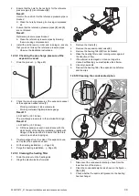
12.4
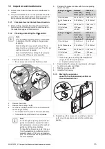
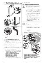
Moving the expansion vessel to the
maintenance position on the hydraulic block
A
C
A
B
D
▶
Depending on the components on which you want to
work, move the expansion vessel to the maintenance
position.
12.5
Cleaning/checking the components
Carry out the preparatory work before cleaning/checking any
of the components.
▶
Prepare the cleaning and inspection work. (
Carry out the work required to finish the task after clean-
ing/checking any of the components.
▶
Complete the cleaning and inspection work. (
12.5.1 Preparing the cleaning and inspection work
1.
Drain the product when you are carrying out work on
hydraulic components. (
2.
Temporarily decommission the product. (
–
Take all necessary precautions to ensure that it
cannot be switched back on again.
3.
Disconnect the product from the mains power.
4.
Close the service valves of the product.
5.
Remove the front casing. (
6.
Hinge the electronics box downwards.
7.
Protect the electrical components (e.g. the electronics
box) from spraying water.
8.
Use only new seals.
12.5.2 Removing the compact thermal module
Danger!
Risk of death and risk of material damage
caused by hot flue gas.
The seal, insulating mat and self-locking nuts
on the burner flange must not be damaged.
Otherwise, hot flue gases may escape and
cause personal injury and material damage.
▶
Replace the seal each time you open the
burner flange.
▶
Replace the self-locking nuts on the
burner flange each time you open the
burner flange.
▶
If the insulating mat on the burner flange
or on the back panel of the heat ex-
changer shows signs of damage, replace
the insulating mat.
Note
The compact thermal module consists of four
main components:
–
Gas valve assembly,
–
Venturi and restrictor for the reference pressure
pipe,
–
Burner flange,
–
Premix burner.
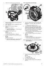
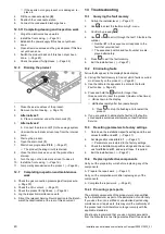
1.
Never remove the venturi from the burner flange.
x4
3
5
4
2
1
6
2.
Remove the plug
(5)
from the gas valve assembly.
3.
Remove the plug
(4)
from the ignition device.
4.
Remove the earth cable
(3)
from the ignition electrode.
5.
Unscrew the union nut
(6)
from the gas valve
assembly.
Summary of Contents for Compact 24c-AS/1
Page 59: ......


