12
221462C
5 Electrical Wiring
6.1 All Systems
Make sure that the system has been thoroughly flushed out with
cold water without the pump in place. Refit the pump, fill the
system with water, making sure that all the air properly vented
from the system and pump.
Before operating the boiler make sure that all external controls
are calling for heat.
6.2 Sealed Water Systems Only
Flush the whole system with cold water without the pump in
place. Refit the pump and fill until the pressure gauge registers
1.5bar (21.5lbf/in
2
). Clear any airlocks and check for water
soundness.
Check the operation of the safety valve, by allowing the water
pressure to rise until the valve opens. The valve should open
/-0.3bar (+/-4.3lbf/in
2
) of the 3bar preset pressure.
Where this is not possible conduct a manual check and test.
Release cold water to initial system design pressure.
The set pointer on the pressure gauge should be set to coincide
with the indicating pointer.
6.3 Initial Lighting and Testing - All Systems
Refit the outer case, see diagram 4.1.
Identify the controls be reference to diagram 6.1.
Turn the control thermostat control knob “A” to “O” the Off
position, see diagram 6.1.
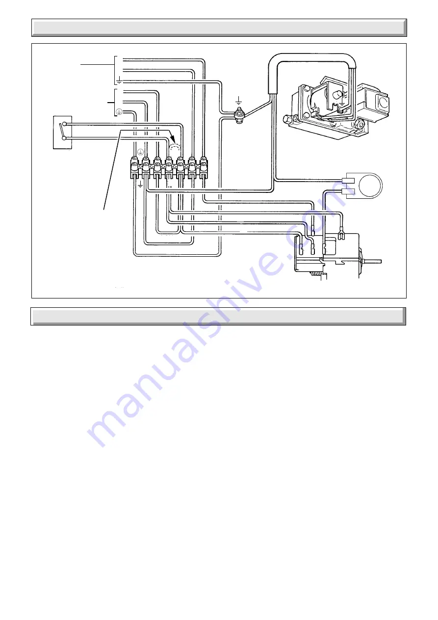
Diagram 5.2
WIRING DIAGRAM FOR CONTROL BOX.
SWITCHED
CONTROL
TIME SWITCH
PROGRAMMER
ETC.
(if fitted)
CIRCULATION
PUMP
240V~ 50Hz
PERMANENT
MAINS SUPPLY
FUSED AT 3A
L
N
L
N
BROWN
BLUE
GRN/YEL
GAS VALVE
BROWN
BROWN
RED
RED
PURPLE
BLUE
BROWN
BLUE
GRN/YELLOW
CHASSIS
EARTH
POST
3
7
6
8
9
Remove Red Link
between 9 and SL
when fitting a time
control etc.
(If link is not
removed the
circulation pump
will run constantly. )
7
8
9
7
8
9
N
L SL
N
L
SL
COMBINED THERMOSTAT AND
PUMP OVERRUN
5353
GRN/YELLOW
BROWN
BLUE
WHITE
F.B.S.D.
Remove the pressure test point screw “K” and fit a suitable
pressure gauge.
Turn the electrical supply on and check that the pump is
working.
Open all windows and put out any naked lights, pipes, cigarettes
and the like.
Turn on the main gas supply and purge in accordance with the
current issue of BS6891.
Turn the boiler gas service cock “J” to On.
Note. Make sure that the flue blockage safety device reset
button “M” is fully pushed in.
Push in control button “B”, keep pushed in and at the same time
operate the piezo button “C” until the pilot burner lights. After the
pilot burner lights keep the button “B” pushed in for about 15
seconds. If the pilot burner fails to light or stay alight a safety
device prevents immediate relighting. Do not attempt to relight
until the safety device has reset.
Note. Should the boiler fail to operate correctly refer to Fault
Finding Section.
Check the length of the pilot flame, it should envelop the
thermocouple tip as shown in diagram 7.7. The pilot rate can be
adjusted by turning screw “H”, having first removed the gas
valve cover by releasing the screws, see diagram 6.1.
Test pilot supply connections for soundness with a suitable leak
detection fluid.
6 Commissioning


