background image

16

221462C

7 Servicing and Replacement of Parts

7.4 Pilot Burner and Injector - Service

Generally follow the instructions given in Section 7.1.

With the main case, inner case and controls cover etc., removed
as above, pull off ignition lead from the electrode.

Unscrew the tubing nut at the base of the pilot burner, releasing
the pilot pipe.  Remove the pilot injector by unscrewing from the
pilot burner.

Unscrew the thermocouple nut to release the thermocouple
from the pilot burner.

Support the main burner and remove the two screws and
washers securing the pilot burner and shield to burner.

Remove the complete assembly.

Lift the pilot burner off.

Take care not to damage the electrode.

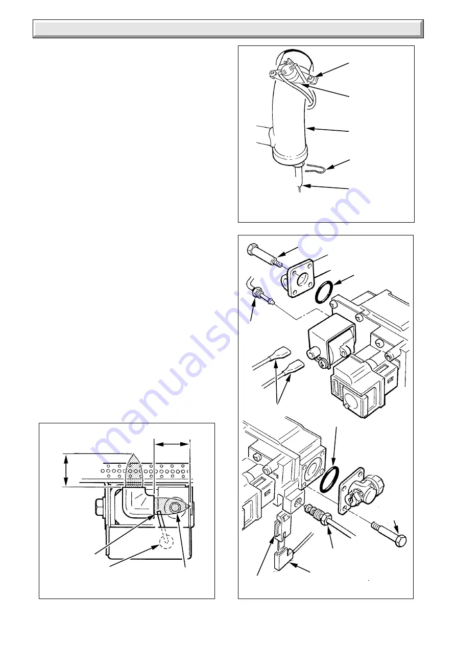
When replacing make sure the spark gap is as shown in diagram
7.7.

Check the pilot burner flame lengths are as shown in diagram
7.7.

7.5 Thermocouple

Generally follow the instructions given in Section 7.1.

Unscrew the thermocouple nut to release from the pilot burner,
see diagram 7.3.

Disconnect the thermocouple from the gas valve, see diagram
7.9.

Use the old thermocouple as a pattern when fitting the new one.
Do not tighten more than a quarter turn beyond finger tight at the
gas valve.

Check the electrode spark gap, see diagram 7.7.

Diagram 7.7

PILOT FLAME AND
SPARK GAP

14 to 17mm

14 to 17mm

THERMOCOUPLE

ELECTRODE

SPARK GAP
3 TO 4mm

1053

Diagram 7.8

THERMOSTAT
PHIAL/OVERHEAT
CUT-OFF

OVERHEAT
CUT-OFF

HEAT
EXCHANGER

RETAINING
CLIP

THERMOSTAT
PHIAL

CUT-OFF
SECURING
SCREW(S)

0951

GAS VALVE ASSEMBLY

Diagram 7.9

GAS SERVICE
COCK
(Shown Off)

'O' RING

INTERRUPTER

EXT. SCREW (4)

'O' RING

PILOT
TUBE
NUT

GAS
VALVE
CONNECTORS

THERMOCOUPLE NUT

ELECTRICAL
CONNECTOR

2414

EXT.
SCREW (4)

Summary of Contents for economy plus c 50

Page 1: ...l Customer Service number 01773 828100 Our Guarantee gives you peace of mind plus valuable protection against breakdown by covering the cost of Guarantee Registration Open Flue Boiler This is a Cat I2H Appliance BS 6332 BS 5258 Reference in these instructions to British Standards and Statutory Regulations Requirements apply only to the United Kingdom For Ireland the rules in force must be used To ...

Page 2: ...F which are man made vitreous silicate fibres Excessive exposure to these materials may cause temporary irritation to eyes skin and respiratory tract consequently it makes sense to take care when handling these articles to ensure that the release of dust is kept to a minimum To ensure that the release of fibres from these RCF articles is kept to a minimum during installation and servicing we recom...

Page 3: ...reezing up If an immersion heater is fitted in the domestic hot water cylinder make sure that it is switched off If you have a sealed water system you should contact your installer servicing company as a sealed water system should only be drained refilled and pressurised by a competent person Boiler Clearance The boiler must be positioned so that at least the minimum operational and servicing clea...

Page 4: ...ockage safety device may also need resetting refer to safety device instructions Make sure that the pilot is alight and stable Switch on the electrical supply to the boiler Check that all external controls are calling for heat Turn control thermostat knob A fully clockwise to MAX and the main burner will light fully in about three to five seconds look through window D If the main burner does not l...

Page 5: ...ons applicable in Scotland local Water Company Byelaws The HealthandSafetyatWorkAct ControlofSubstancesHazardous to Health The Electricity at Work Regulations and any local applicable regulations Detailed recommendation are contained in the current issue of the following British Standards and Codes of Practice BS4814 BS5400 Part and 2 BS5449 BS5446 BS6700 BS6798 BS6891 BS7074 Part and 2 BS7478 BS7...

Page 6: ...PVC flexible type to the current issue of BS6500 Table 16 not less than 0 75mm2 24 0 20mm 1 9 Draining Tap A draining tap must be provided at the lowest points of the system which will allow the entire system boiler and domestic hot water cylinder to be drained Draining taps shall be to the current issue of BS2879 1 10 Safety Valve A safety valve need not be fitted to an open vented system 1 11 Cl...

Page 7: ...r Where the boiler is fitted in a cupboard or compartment permanent high and low level ventilation must be provided The minimum ventilation areas required are given in Table A 2 2 Boiler Installed in a Room or Space Apurposedesignedventilationopeningmustbeprovidedonan outside wall of the premises refer to the current issue of BS5440 Part 2 for further information The opening may be either directly...

Page 8: ...ndations for the best product to use When installing a boiler in an existing system whether or not using an inhibitor take special care to drain the entire system including the radiators then thoroughly cleaning out before fitting the boiler and adding the inhibitor 3 4 Sealed Water Systems Theinstallationshouldcomplywiththeappropriaterequirements of the current issue of BS4814 BS5449 BS6759 BS679...

Page 9: ...tem that is the height of the highest point of the system above the expansion vessel The water capacity of the boiler is given in Section 1 3 7 Pressure Gauge A pressure gauge with a set pointer and covering at least the range of 0 to 4 bar 0 to 60lb in2 shall be permanently fitted to the system in a position where it can be seen when filling the system 3 LITRES 0 66 gals MAKE UP BOTTLE if require...

Page 10: ...f the domestic hot water cylinder Alternatively provision for make up can be made by using a filling loop 3 10 Filling a Sealed Water System Provision for filling the system at low level must be made Three methodsareshownindiagram3 5 Theremustbenopermanent connection to the mains water supply even through a non return valve 4 1 Appliance Preparation Remove the controls cover by pulling it forwards...

Page 11: ... cable clamp When making connections make sure that the earth conductor ismadeofagreaterlengththanthecurrentcarryingconductors so that if the cable is strained the earth conductor would be the last to become disconnected 5 2 Pump and External Controls Connections The pump must be wired into the boiler control box as shown in diagram 5 2 AnyexternalcontrolsmustonlybewiredtointerrupttheRedlink betwe...

Page 12: ... N L N BROWN BLUE GRN YEL GAS VALVE BROWN BROWN RED RED PURPLE BLUE BROWN BLUE GRN YELLOW CHASSIS EARTH POST 3 7 6 8 9 Remove Red Link between 9 and SL when fitting a time control etc If link is not removed the circulation pump will run constantly 7 8 9 7 8 9 N L SL N L SL COMBINED THERMOSTAT AND PUMP OVERRUN 5353 GRN YELLOW BROWN BLUE WHITE F B S D Remove the pressure test point screw K and fit a...

Page 13: ...ER BUTTON G VIEWING WINDOW H GAS RATE ADJUSTMENT SCREW UNDER COVER SCREW J GAS SERVICE COCK K PRESSURE TEST POINT L PILOT BURNER ADJUSTMENT SCREW M FLUE BLOCKAGE SAFETY DEVICE RESET SWITCH M Diagram 6 1 5354 6 5 Flushing Allow the system to reach maximum working temperature and examine for water leaks The boiler should then be turned off and the system drained as rapidly as possible whilst still h...

Page 14: ...vice or replacing parts isolate the gas and electrical supplies Unless stated otherwise all parts are replaced in the reverse order to removal 7 1 Heating Body Service Remove the controls cover by pulling it forwards and off Remove the outer casing by releasing the screw at the bottom and unhooking at the top Remove the inner casing by releasing the wing nuts at the top and the screws at the botto...

Page 15: ...manifold Diagram 7 2 ACCESS FOR SERVICING Diagram 7 3 PILOT ASSEMBLY PILOT INJECTOR ADAPTOR OLIVE PILOT TUBING NUT THERMOCOUPLE NUT IGNITION LEAD clear end ELECTRODE THERMOCOUPLE SECURING SCREWS PILOT SHIELD MICA WINDOW M3 SCREW COMBUSTION CHAMBER FRONT PANEL SIDE BAFFLES SECURING SCREWS WING NUT 2397 1049 Diagram 7 4 DRAUGHT DIVERTER AND BAFFLE BAFFLE SECURING SCREW S DRAUGHT DIVERTER BAFFLE 0929...

Page 16: ...hownindiagram 7 7 Check the pilot burner flame lengths are as shown in diagram 7 7 7 5 Thermocouple Generally follow the instructions given in Section 7 1 Unscrew the thermocouple nut to release from the pilot burner see diagram 7 3 Disconnect the thermocouple from the gas valve see diagram 7 9 Use the old thermocouple as a pattern when fitting the new one Do not tighten more than a quarter turn b...

Page 17: ...withdraw the phial see diagram 7 8 Remove the control box by undoing the two fixing screws at the front and lower the front of the box until it is clear of the cover Push the box towards the rear of theboilertodisengagethehinge and lower see diagram 5 1 Withdraw the control thermostat capillary through the bottom of the air duct Disconnect cables a mains L N and E b pump at terminal 8 7 and earth ...

Page 18: ...rew s Inset B Carefully remove phial and capillary through back of boiler Inset C Having opened control box remove the electrical connections from the flue blockage safety device the locknut and capillary retaining clip Fit new flue blockage safety device in reverse order making sure that the capillary is secure and there is sufficient slack at the control box to allow the box to be opened and clo...

Page 19: ... on maximum control thermostat setting Change faulty overheat cutoff device The correctly set overheat cutoff device operates prematurely There is no air in the heating body and water circulation satisfactory Change faulty heating body Pump not functioning correctly Check pump is wire directly to the boiler Alter system if necessary 8 5 Insufficient Heat Control thermostat set too low Increase set...

Page 20: ...e continuity YES NO NO 8 7 Thermocouple and Overheat Cutoff Device To test the thermocouple a meter with a range of 0 to 30 mV is required Symptom The pilot burner fails to stay alight Test the thermocouple overheat cutoff and thermocouple connectors as described in fault finding chart 8 2 see also diagram 8 1 Check the millivoltage of the thermocouple closed circuit at points A and E see diagram ...

Page 21: ...y Device if faulty repair or renew Turn ON thermostat Does main burner light Turn ON thermostat With appliance cold Is there 240V between 7 and N Turn ON thermostat Is there 240V between 7 and N MAIN TERMINAL STRIP THERMOSTAT TERMINALS Faulty thermostat renew Faulty cable RED from terminal block to thermostat repair or renew Faulty cable RED from terminal block to thermostat repair or renew Faulty...

Page 22: ...CONTROLS IN ORDER Faulty Cable PURPLE between thermostat and terminal block repair or renew Faulty pump inform customer Faulty thermostat renew YES YES YES NO NO NO YES Continued Continued MAIN TERMINAL STRIP THERMOSTAT TERMINALS NO Electrical Fault Finding Continued 4403A 5393 PERMANENT LIVE 240V 50 Hz FUSED AT 3A RED LINK If no switch control is used MAIN TERMINAL STRIP THERMOSTAT TERMINALS SWIT...

Page 23: ...ATISFACTORY Does pilot flame envelop thermocouple Check aeration If necessary Clean pilot rectify blockage in pilot injector or replace Check thermocouple circuit using Thermocouple and Boiler Overheat Cut off fault finding diagram On pressing piezo unit button is there a spark across electrode gap Pull ignition lead off electrode Hold end of lead close to pilot burner and operate piezo unit Is th...

Page 24: ...t cutoff device 313 064 5 800015 Gas valve assembly inc 14 313 067 6 900000 Thermocouple 394 162 7 203415 Pilot burner inc 12 394 161 8 202600 Electrode 384 149 9 416144 Control thermostat knob 355 401 10 WW4612 Ignition lead 355 500 11 203040 Injector 50C 398 513 12 203509 Pilot injector 394 163 13 411194 Sight glass 355 153 14 208040 O ring gas valve 334 592 15 203350 Solenoid 313 226 16 800786 ...

Reviews: