0020239562_04 EASICOM 3 Installation and maintenance instructions
21
7.7
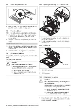
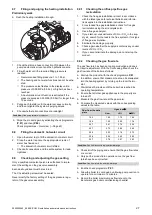
Connecting the drain cock
1
▶
Connect a hose to the drain cock
(1)
and guide the free
end of the hose to a suitable drainage point.
7.8
Flue installation
7.8.1
Installing and connecting the air/flue pipe
1.
You can find out which air/flue pipes may be used by
consulting the enclosed set-up instructions for the
air/flue system.
2.
Observe the information on positioning the air/flue ter-
minal.
Condition
: Installation in damp rooms
▶
You must connect the product to a room-sealed air/flue
system. The combustion air must not be taken from the
installation site.
3.
Install the air/flue pipe using the set-up instructions.
7.9
Electrical installation
Only qualified electricians may carry out the electrical install-
ation.
The product must be earthed.
Danger!
Risk of death from electric shock!
The power supply terminals L and N remain
live even if the product is switched off:
▶
Switch off the power supply.
▶
Secure the power supply against being
switched back on.
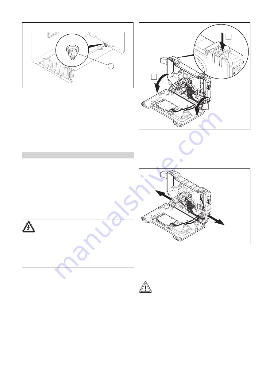
7.9.1
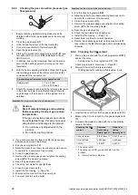
Opening and closing the electronics box
B
B
A
1.
To open the electronics box, follow the instructions in
the specified sequence.
2.
To close the electronics box, follow the instructions in
reverse order.
7.9.2
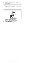
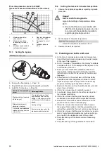
Cable route
230V
24V / eBus
1
24-V eBUS cable route
2
230 V cable route
7.9.3
Carrying out the wiring
Caution.
Risk of material damage caused by incor-
rect installation.
Mains voltage at incorrect terminals and plug
terminals may destroy the electronics.
▶
Do not connect any mains voltage to the
eBUS terminals (+/-).
▶
Only connect the power supply cable to
the terminals marked for the purpose.
1.
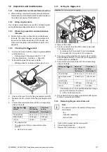
Route the connection cables of the components to be
connected through the grommet provided on the under-
side of the product on the left.
Summary of Contents for EASICOM 3 24c
Page 1: ...en Installation and maintenance instructions EASICOM 3 24c 28c 0020239562_04 31 07 2020 ...
Page 54: ......
Page 55: ......

