Installation 5
0020201109_01 Energy Installation and maintenance instructions
11
7
6
5
4
3
2
1
1
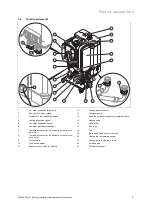
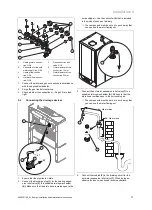
Heating return connec-
tion, G3/4
2
Connection for the cold
water supply line, G3/4
3
Heating flow connec-
tion, G3/4
4
Hot water flow connec-
tion, G3/4
5
Gas connection with
valve, G1/2
6
Outer diameter of the
connection 15 mm
7
Outer diameter of the
connection 22 mm
1.
Connect the water and gas connections in accordance
with the applicable standards.
2.
Purge the gas line before start-up.
3.
Check whether the connections (
→
Page 20) are leak-
tight.
5.2
Connecting the drainage devices
A
1
1
2
3
1.
Ensure that the pipeline is visible.
2.
Connect the discharge pipe
(1)
for the heating expan-
sion relief valve
(2)
to a suitable draining mechanism
(A)
. Make sure that the drain hose remains open to the
surrounding air. Use the connector
(3)
that is included
in the product's scope of delivery.
◁
The components must be set up in such a way that
you can see the water flowing out.
A
1
3.
Connect the hot water expansion relief valve
(1)
to a
suitable draining mechanism
(A)
. Make sure that the
drain hose remains open to the surrounding air.
◁
The components must be set up in such a way that
you can see the water flowing out.
D1: 600 mm max.
D2: 300 mm min.
1
2
4.
Connect the tundish
(2)
to the draining circuit for the
hot water expansion relief valve
(1)
. When doing so,
observe the above-mentioned recommendations.

