7 Adapting the unit to the heating installation
20
Installation and maintenance instructions Energy 0020201109_01
Overview of diagnostics codes (
→
Page 28)
▽
Contact Customer Service if the gas flow rate does
not correspond to the value specified on the inform-
ation plate.
–
Permissible tolerance for fan speed:
−
200
… 200 rpm
4.
Press the menu button for 3 seconds to go to the check
programme.
6.12
Checking function and leak-tightness
Before you hand the product over to the operator:
▶
Check the gas line, the flue gas installation, the heating
installation and the hot water pipes for leaks.
▶
Check that the air/flue pipe and condensate drain pipe-
work have been installed correctly.
▶
Check that the front casing has been installed correctly.
6.12.1 Checking the heating mode
1.
Activate the heating mode on the user interface.
2.
Turn all thermostatic radiator valves on the radiators
until they are fully open.
3.
Start up the product.
–
Product operating period:
≥
15 min
4.
Check the current operating status code.
Status codes
–
Overview (
→
Page 30)
◁
If the product is working correctly, the display shows
S.04.
6.12.2 Checking the hot water generation
1.
Activate the hot water handling mode on the user inter-
face.
2.
Open a hot water valve completely.
3.
Activate the display for the current operating status.
(
→
Page 25)
Status codes
–
Overview (
→
Page 30)
◁
If the product is working correctly, the display shows
S.24.
7
Adapting the unit to the heating
installation
7.1
Using diagnostics codes
You can use the parameters marked as adjustable in the
table of diagnostics codes to adapt the product to the system
and customer requirements.
Overview of diagnostics codes (
→
Page 28)
7.1.1
Activating diagnostics codes
1.
Press the menu button for 7 seconds to go to the set-
tings for the product's diagnostics codes.
◁
(0)
appears in the display.
2.
Press the
or
button to select the setting
value.
◁
The access code
(96)
is reserved for the competent
person.
3.
Press the menu button to confirm.
◁
The diagnostics code and its value appear in the
display.
7.1.2
Setting a diagnostics code
1.
Press
or
button to select the diagnostics
code.
2.
Press the
or
button to select the setting
value.
3.
Proceed accordingly for all parameters that need to be
changed.
4.
Press the menu button for 3 seconds to exit the para-
metrisation menu.
7.2
Setting the pump output
The product is equipped with a speed-regulated high-effi-
ciency pump, which adjusts independently to the hydraulic
conditions of the heating installation.
If you have installed a low loss header in the heating install-
ation, we recommend switching off the speed regulation and
setting the pump output to a fixed value.
▶
If required, change the setting for the pump speed, which
depends on the operating mode, using diagnostics code
d.14.
▶
Set a diagnostics code. (
→
Page 20)
Overview of diagnostics codes (
→
Page 28)
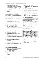
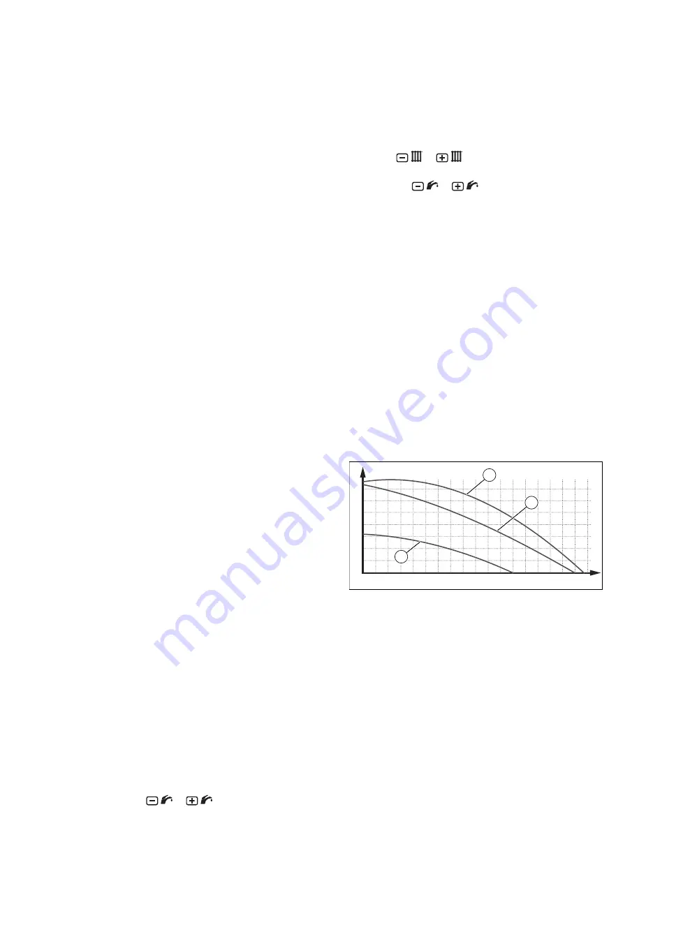
Pump characteristic lines
Flow rate-pressure curve
60
70
50
40
30
20
10
0
500
1000
1500
A
B
2
1
3
A
Heating circuit flow rate
(l/hr)
B
Available pressure
(kPa)
1
Bypass closed, max.
PWM
2
Bypass in series set-
ting, max. PWM
3
Bypass in series set-
ting, min. PWM


