Appendix
0020201109_01 Energy Installation and maintenance instructions
33
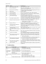
Fault
Possible causes
Remedial action
Traces of water un-
der the product
Condensate drain pipework blocked
Check the condensate discharge pipe and clean it if necessary.
Leak in the system or the product
Close the product's cold water inlet and identify the cause of the leak.
Drain valves not connected correctly
Check the valve connection.
G
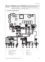
Connection diagram: Model -A
1
10
2
11
3
12
4
13
5
14
6
15
7
16
8
17
9
18
1 2
3 4
10 9 8 7 6 5 4 3 2 1
19
20
18 17 16 15 14 13 12 11
M
M
T
T
T°C
NTC
Ebus
24 V
X2
X30
X90
X32
X40
X51
X31
X21
230 VAC
L
N
X12
X101
FUS
X14
X20
X18
X17
X17
1
4
2
5
3
6
10 9 8 7 6 5 4 3 2 1
19
20
18 17 16 15 14 13 12 11
1 2
3
4
2 1
X2
3
4
5
2 1
1
1
1
1
...
8
9
2 1
1
10
2
11
3
12
4
13
5
14
6
15
7
16
8
17
9
18
X20
1 2
3 4
1
1 2
1
X21
X13
M
1
1
NTC
1
1
NTC
1
2
3
4
5
6
7
8
9
11
12
13
14
15
16
17
18
20
19
10
1
Plug for the safety thermostat
2
Plug for control accessories
3
Exalink plug
4
Plug for temperature sensor
5
PCB for 24V options
6
User interface
7
Fuse
8
Plug for 230V options
9
Pump plug
10
Hot water pump plug


