Change of main power connection
Standard wiring 3W+N+PE
•
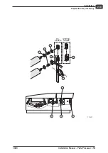
On arrival the processor is wired as shown
opposite. Connect the power cords to
terminals L1, L2, L3, N and PE.
Changing from 3W+N+PE to 2W+PE (single
phase)
•
See the opposite illustration.
–
Move the brown wire from terminal 5 and
mount it in terminal 3 together with the
yellow wire.
–
Move the blue, orange and black wires
from terminal N
(a)
to terminal 5.
–
Mount jumper (see spare parts box) from
terminal 4 to terminal N.
–
Move the blue wire from terminal N
(b)
and mount it in terminal 6 together with
the brown wire.
–
Locate the terminal strip
(X7)
.
–
Mount jumpers between terminal L1 and
L2 and between L3 and N.
–
Connect the power supply cable to
terminal L1 adn L3 and PE.
"
For an installation without neutral wire, fuses F33, F34, F35, F36, F 37 and F38
must be installed. Jumpers x69, x70,c x71, x72x x73 and x74 located on the fuse
PCB must be removed.
1049
Installation Manual - Plate Processor 150
2-13
Installation
Electrical specifications
2
1
2
3
4
X7
F10
1
RED
YELLOW
BROWN
BLUE
ORANGE
BLACK
4
3
6
5
10
12
8
6
4
2
T
L1
L2
POWER SUPPLY CONNECTION
FOR 3W+N+PE (standard)
L3
N
PE
RED
YELLOW
BROWN
BLUE
Main switch
To X3
on fuse PCB
N
N
T2612
b
a
2
1
2
3
4
X7
F10
1
RED
YELLOW
BROWN
BLUE
ORANGE
BLACK
4
3
6
5
10
12
8
6
4
2
T
L1
L2
POWER SUPPLY CONNECTION
FOR 3W+N+PE (standard)
L3
N
PE
RED
YELLOW
BROWN
BLUE
Main switch
To X3
on fuse PCB
N
N
T2612
b
a


