D1014
- SIL 2 Repeater Power Supply Hart compatible
G.M. International ISM0052-16
9
1
2
3
4
ON
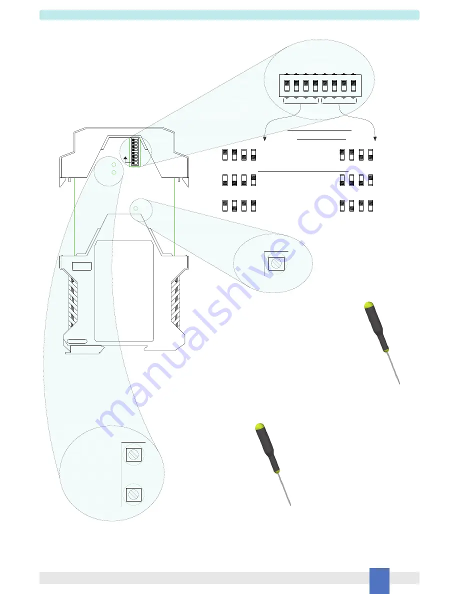
Switch positions
Ch1 4-20 mA
Source Mode
6
7
8
5
1
2
3
4
6
7
8
5
1
2
3
4
6
7
8
5
1
2
3
4
6
7
8
5
Ch1 4-20 mA
Sink Mode
Ch2 4-20 mA
Source Mode
Ch2 4-20 mA
Sink Mode
Ch2 1-5 V
(on 250
---
internal shunt)
Ch1 1-5 V
(on 250
---
internal shunt)
An output configuration DIP Switch is located on component side of pcb. This switch allows the mA (sink or source mode) or Volt operating mode configuration.
Configuration
Side A Panel View
Span Trimmer
CH1
Screwdriver
for Trimmers
1 x 0.5 mm
Dip switch configuration
Ω
Ω
Vtx Adjust Ch1
Screwdriver
for Trimmers
2 x 0.5 mm
Zero Trimmer
CH1
Calibration Trimmer Ch1
Turn the trimmer clockwise to
Increase Output value or turn
the trimmer counterclockwise
if you want to decrease Output
value.
Turn the trimmer clockwise to
Increase Output value or turn
the trimmer counterclockwise
if you want to decrease Output
value.
ON
Sink/Source for SIL applications
Source Current Output
is factory settings


