D1049
- SIL 3 Digital Output Driver NE Loads Bus Powered
G.M. International ISM0097-9
5
For installations in which both the Ci and Li of the Intrinsically Safe apparatus exceed 1 % of the Co and Lo parameters of the Associated Apparatus (excluding the cable),
then 50 % of Co and Lo parameters are applicable and shall not be exceeded
(50 % of the Co and Lo become the limits which must include the cable such that
Ci C cable
≤
50 % of Co and Li L cable
≤
50 % of Lo).
If the cable parameters are unknown, the following value may be used: Capacitance 60pF per foot (180pF per meter), inductance 0.20µH per foot (0.60µH per meter).
The Intrinsic Safety Entity Concept allows the interconnection of Intrinsically Safe devices approved with entity parameters not specifically examined in combination as a system
when the above conditions are respected.
For Division 1 and Zone 0 installations, the configuration of Intrinsically Safe Equipment must be FM approved under Entity Concept (or third party approved);
for Division 2 installations, the configuration of Intrinsically Safe Equipment must be FM approved under non-incendive field wiring or Entity Concept (or third party approved).
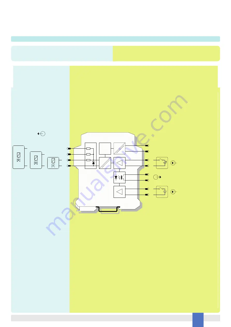
Function Diagram
HAZARDOUS AREA ZONE 0 (ZONE 20) GROUP IIC,
HAZARDOUS LOCATIONS CLASS I, DIVISION 1, GROUPS A, B, C, D,
CLASS II, DIVISION 1, GROUPS E, F, G, CLASS III, DIVISION 1,
CLASS I, ZONE 0, GROUP IIC
SAFE AREA, ZONE 2 GROUP IIC T4,
NON HAZARDOUS LOCATIONS, CLASS I, DIVISION 2,
GROUPS A, B, C, D T-Code T4, CLASS I, ZONE 2, GROUP IIC T4
Use only one output at a time
(Out A or Out B or Out C)
MODEL D1049S
15
16
5
6
+
-
Solenoid
Valve
=
=
In 1
Control
14
13
Out 1
+
-
+
-
--
+
Solenoid
Valve
Solenoid
Valve
+
-
1 +
2 -
Transistor Fault Out
Out C
Out B
Out A
Load
Diag.
7
8
Override
+
-
3 +
4 - Supply 24 Vdc
=
=


